About OPC Client Channels
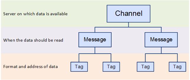
OPC Client Channels are used to create named connections to the shop floor via an OPC Server. These connections are called tags. In order to create a tag you need to specify the server on which the data exists, the format of the data, when the data should be read and the address of the data.
This information is specified in different layers as shown below where the channel contains messages which contain the tags:
ATS Bus can handle OPC connections using either the more recent OPC Unified Architecture (UA) specifications or the legacy OPC Data Access (DA) specifications.
Redundant OPC Servers
ATS Bus 2.7 and onwards support redundant OPC servers for high available connections. The channel can be configured to handle the following scenarios:
Stay on the active endpoint till it fails. (start on the primary endpoint and switch to the secondary when it fails. Do not reconnect to the primary if that endpoint is available again but stay on the secondary node).
Return to the primary node as soon as it is active.
The OPC Channel will fail over when:
it misses an OPC Server keep alive message (lost connection to OPC server).
an OPC tag state changes to bad quality.
an OPC tag value has a certain value (condition evaluation for tag value)
OPC Specification Types
Using OPC DA Specifications
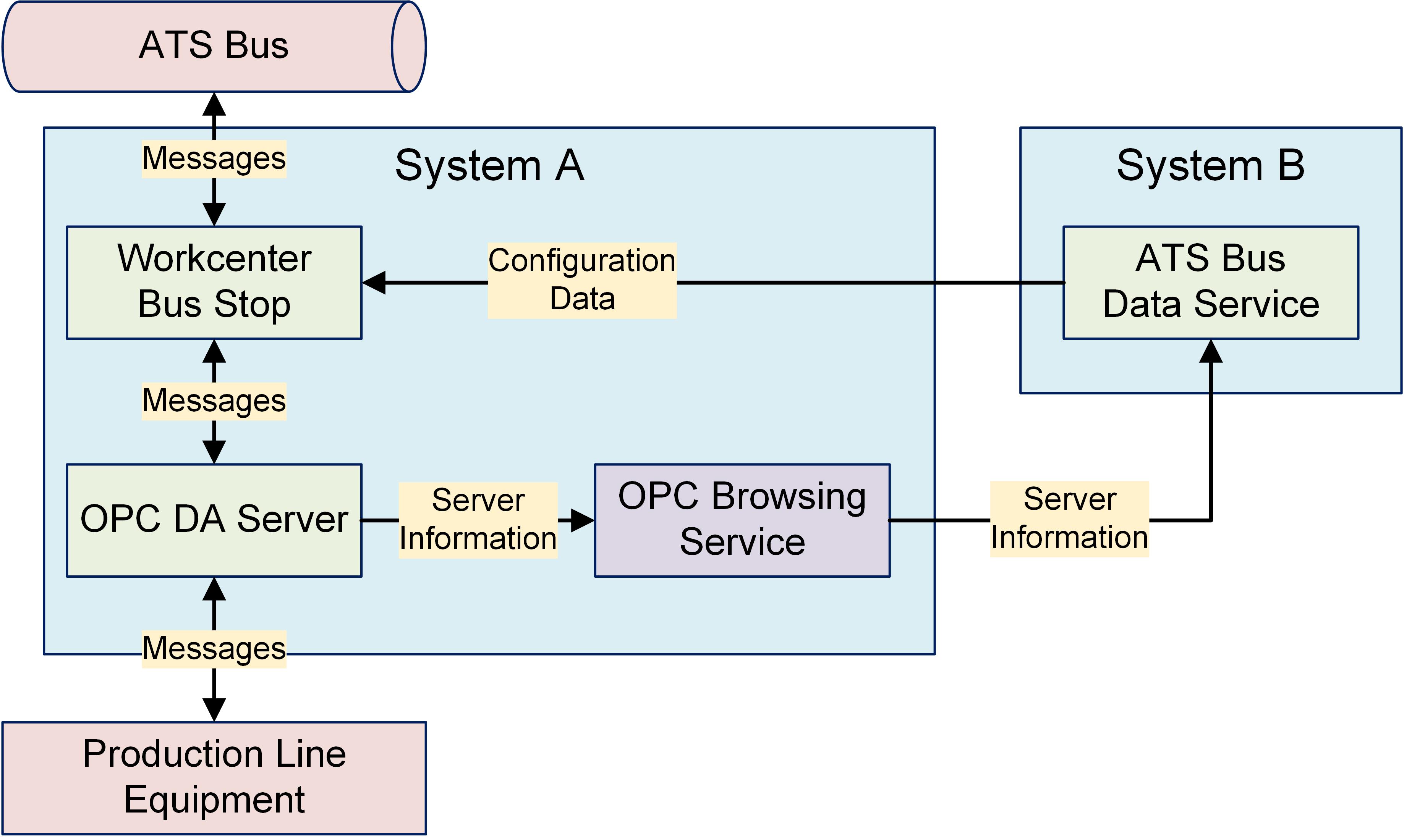
In order to use OPC DA specification the OPC Browsing Service must be installed. ![]()
The OT bus stop must be installed on the same system as the OPC DA server because the OPC channels do not support remote OPC servers.
ATS Bus Cockpit queries the OPC DA server through the ATS Bus Data Service which relays the ‘queries’ to a service named OPC Browsing Service. This service is available as a separate installer and should be installed on the same host as where the OPC Server is installed. The OPC Browsing Service invokes OpcEnum (an OPC foundation OPC server enumerator) to query the available OPC servers on that host.
Using OPC UA Specifications
One of the advantages of OPC UA specification is that the OT Bus Stop can be installed on a separate host to the OPC UA server.
A Local Discovery Server (LDS) is optional, but the OPC UA Channel can query an OPC UA endpoint directly without using a LDS.
A trust has to be setup between the LDS and OPC UA Server and the OPC UA Server and the OT Bus Stop OPC UA channel. For information please refer to the section Create Trust Between UA Server, UA Client and LDS. 

Create an OPC Client Channel
Select the OT Bus Stop tab.
Click OPC Channels.
A list of the existing OPC channels is shown.
Click Add.
A new window opens.
Enter a name for the channel.
Select OPC DA or OPC UA.
Configure the primary endpoint, see OPC DA specific channel configuration and OPC UA specific channel configuration.
Tick the checkbox ‘Enable failover’ when a redundant OPC Server is must be configured, this will bring up the ‘Failover settings’ section. This section allows to configure the secondary endpoint and the failover behaviour:
Select or create a secondary endpoint.
Tick the Return to the primary endpoint as soon as it is active checkbox when the channel must ‘return’ to the primary endpoint as soon as it is available. See How does the Return to primary endpoint as soon as it is active work?
Choose one of the options to fail over to the alternative node:
Fail over on missing OPC server keep alive: Fail over to the alternative node when the channel misses the OPC server keep alive message.
Fail over when the Failover tag quality changes to something else than 'Good'. The channel should fail over to the alternative node when the Failover tag quality changes to a value other than good (192).
Fail over when the Failover tag expression yields to true: The channel should fail over to the alternative node when the expression given by Failover tag evaluates to true.
The Failover tag configuration is available through the “...” button, see Failover Tag for more information
Enter a description in the default language and any other required languages.
Add channel messages as described in the section Add a channel message.
OPC DA specific channel configuration
Provide a name for the connection.
Enter the Browsing Host. This is the hostname of the computer that hosts the OPC Browsing Service.
Enter the Browsing Port. This is the port where the browsing service listens.
Enter the OPC Server Host. This is the hostname of the computer that is running the OPC Server.
Click Refresh to update the list of OPC servers.
Select the OPC Server from the drop-down list.
If required, enable Reconnect to the OPC server if keepalive messages are missing for more than the configured interval and specify an interval in minutes. If there is no response from OPC server for time longer than the specified interval then reconnection is started. If the server does not support keepalive or you don’t want this behaviour simply uncheck the option.
OPC UA specific channel configuration
Provide a name for the OPC UA connection endpoint.
Select a Discovery mode. This can be either:
Use Local Discovery Server: Use when local discovery server is available (A LDS is not installed by ATS Bus).
Use Endpoint Discovery: Use for direct OPC Server endpoint selection.
Enter the host and port of either the Local Discovery Server (LDS) or the OPC Server. (By default the LDS service is on port 4840). The Discovery path option is only available when the discovery mode is set to Use endpoint discovery. It adds a path to the discovery endpoint: e.g. opc.tcp://hostname:49320/Discovery.
Click Refresh to update the list of servers.
A dialog asking to trust the OPC Server may appear. Click Yes if you trust the server.
Select the OPC Server from the drop-down list.
You must log on to the OPC UA Server machine and trust the client application named ATS Bus OPC UA Client. This certificate is installed when selecting Yes in the previous step. You must also logon to the OPC UA Server machine and trust a second client application named ATS Bus OPC UA Client, when starting an OT bus stop.
Select an Endpoint Address. Endpoints specify which security policy is used for communication (signing and encryption).
Place a tick in the Check domain check box to compare the OPC endpoint URL with the OPC Server certificate domains. If the details provided do not match, an exception is thrown and the secure connection is not established.
The Reject SHA1 server certificates check box is ticked by default. To allow SHA1 server certificates, remove the tick.
SHA1 certificates are found with older OPC servers. To verify, check the certificate properties in the OPC UA server.
OPC UA Client channel endpoint definition offers a field to set a minimum certificate key size. By default it is set to 2048. To allow certificates with a lower value it is necessary to change the value in the field.
The OPC foundation libraries have a restriction to only allow certificates that have a minimum key size equal or greater than 2048. Certificates with key size less than 2048 are found with older OPC servers.
Enter the username and password used to log in to the OPC server. If not provided, the OPC UA client will log on as an anonymous user.
Failover tag

OPC tag: Defines OPC tag for failover detection. Tag browsing is available on “...”. The following properties are available when the OPC specification is set to OPC UA:
Node identifier: Specify tag access path. Mandatory field.
Identifier type: Specify node identifier type (Node path, Numeric Node Identifier or Node GUID). It is preselected when browsing is used for tag selection. Visible and mandatory field for OPC UA specification.
Namespace URI and Namespace index: The OPC server uses a namespace table where the namespaces of the node identifiers are provided. The URI’s in this table are addressed by their index. For further information, please click here. When selecting a tag via the ellipsis of the Node identifier, the Namespace URI and Index are provided (the URI is provided because of historical reasons). When entering a node identifier manually, the Namespace Index must be provided. When providing both the URI and index, the ATS Bus OPC UA functionality ignores the URI and uses the index to obtain the namespace URI.
When using 2 OPC UA servers in a redundant configuration, the Namespace Index must be provided in the tag configuration and not the URI because the URI may only be valid on 1 OPC server because it contains a hostname for instance. Important to understand is that the namespace table is configured in such a way that the namespace indexes point to similar URI’s on both servers. For example, using 2 WinCC OPC servers will work but using a Kepware OPC UA server and a WinCC server may not work if the namespace tables of both OPC UA servers are not aligned.
The following property is available when the OPC specification is set to OPC DA:
AccessPath: Specify the OPC DA access path
Operator: Select operator for tag value comparison. Visible only when Failover detection is set to “Fail over when an OPC tag has a certain value”
Value: Specify a value that should be used to compare with tag value. Visible only when Failover detection is set to “Fail over when an OPC tag has a certain value”
Add a Channel Message
Message Definitions must be created before channel messages can be created. ![]()
Channel messages can be created once an OPC channel has been defined.
While editing an OPC Channel select the Channel Messages tab.
All existing channel messages contained in the channel are listed. The table shows the name of the channel message, the direction in which the message is going and whether or not the message is currently active.
Messages are Uploaded towards the Bus and Downloaded away from it.
Click Add.
Enter a name for the channel message.
The name of the channel message must be unique within the entire ATS Bus configuration.
Select a Message definition. Message Definitions act as templates when adding messages to a Channel. They specify whether the message is being uploaded from equipment or downloaded to equipment and also list the different data fields that will be available in the message.
The Tags control opens. In the right-hand pane it lists the fields contained within the message. The left-hand pane lists tags that will be created that match those fields.
If the field has an Index value associated to it this will be added to the end of the tag name. For example, if the field name is _OperatorID and the field index is Extract then the tag name will be _OperatorID_Extract.
If you don't want tags to be created automatically disable Create remaining tags for message fields.
Use the arrows on the right-hand side to re-order the fields. To refresh the list of tags to match it disable and enable Create remaining tags.
If required, enable Generated tags include data source.
Click Save. You are returned to the New Channel Message window.
Select the Acquisition type and configure the Acquisition settings, these will define how data is exchanged between the channel message and the peer. Please note that the Acquisition types and settings depend on the Direction of the channel message:
Upload
Interval acquisition: Acquisition defined in seconds. The interval must be provided.
Trigger Tag Acquisition: The values of the tags are read when the selected trigger tag changes value. The trigger tags can be specified using the ‘Acquisition settings’.
Simple handshake upload: Apply a simple handshake using a trigger tag.
Double handshake upload: Apply a double handshake using a trigger tag and acknowledge tag.
Rising edge: Start message exchange when the trigger tag goes from zero to non-zero.
Falling edge: Start message exchange when the trigger tag goes from non-zero to zero.
On Change Acquisition: The values of the tags are read when the value of a monitored tag is changed in the channel message.
All tags within the channel message are marked as monitored tags by default. Users can remove the flag for any tags that are do not require monitoring. The monitored flag is only visible for On Change Acquisition.
Scheduled Acquisition: The values of the tags are read at a specific time on a daily, weekly or monthly schedule.
Download
Trigger Tag Acquisition: The values of the tags are downloaded to the OPC client using a handshake. The handshake prevents the channel from downloading new values to the PLC if the trigger is not in an idle state. The trigger tags can be specified using the ‘Acquisition settings’.
Value download: This downloads the channel message directly to the OPC client without using a handshake.
Simple handshake download: Apply a single handshake when downloading the data to the OPC client.
Double handshake download: Apply a double handshake when downloading to the OPC client using a trigger tag and acknowledge tag.
For more information on acquisition settings see here.
If required, enable Handshake Only. This should be selected if the message is to be used for a heartbeat interface.
Enable Active so that the channel message can be used.
Message filtering is available when the Direction of the channel message's message definition is set to Upload. This feature enables conditions to be configured that decides whether or not a channel message is processed. The OPC client channel evaluates the condition as soon as a channel message arrives and processes it if the condition is met.

Clicking the ellipsis on the Filter edit box opens the following dialog where the condition can be configured.
A condition has a left and right operand, an operator and datatype. The Data type specifies the datatypes of both operands (Boolean, Integer), the must be the same.
The left and right operand can use the following data sources:
The actual value from the OPC client
Constant value
Data translation table, converting the actual value from the OPC client to a value configured in the translation table.
Function evaluation, this takes the result of a function that may use the actual value coming from the OPC client.
Bus stop variable
The operator can be:
Less than ‘<’
Less than or equal ‘<=’
Equals ‘==’
Not equal ‘<>’
Greater than or equal ‘>=’
Greater than ‘>’
Add and Modify Tags
ATS Bus 2.7/8 is able to handle OPC Tags of data type Byte[] and SByte[]. When uploading (reading the OPC tag), the channel will convert the byte array into a Base64 encoded string therefore the ATS Bus acquisition data type should be set to string. When downloading (writing the tag), the channel message will decode the Base64 string to an (un)signed byte array. The OPC channel message can be forwarded to an extension channel that processes the Base64 encoded string and creates a new message from it.
The tags provide the link to the location of the data on the server.
Click Add below the Tags pane (or Edit to modify an existing tag).
A new window opens.
Enter the name of the tag in the Description field.
Select a Data Type. This is the format in which the data will be received (e.g. Integer, Text, Char, etc.).
Enable the Active checkbox to ensure the tag is active.
If required, enable Mandatory. If a message is received and a mandatory tag doesn't have a value then the message won't be processed.
The source and destination can now be selected. The source and destination will depend on whether it is an Upload or Download message definition.
Select the Data source and the additional information the data source requires. This can be one of the following:

|
Name |
Description |
Required Information |
|
OPC access path (upload only) |
The value is read from an OPC data source. |
Enter the OPC data source. This can be entered manually or you can click the search button ( |
|
Constant value |
The tag will always be the same value. |
Enter the value to be used. |
|
Data Translation table |
The value is read from an OPC data source and then translated using a data translation table. |
Select the translation table to use and the access path for the source value that will be translated. |
|
Function evaluation |
The value is read from an OPC data source and then modified using a function. |
Enter the function to use and the access path for the source value that will be modified by the function. |
|
Reset counter evaluation |
Instead of sending the received value it sends the iteration. For example, if the last known value was 50 and it receives a value of 53 then the output will be 3. |
No extra information required. |
|
Rollover counter evaluation |
Instead of sending the received value it sends the iteration. As soon as a defined limit is reached the value is reset and the counter goes back to zero. For example, if the current value is 99, rollover is set to 100 and 5 is the incoming value then the result is 6. This is calculated as follows: (100 – 99 + 5 = 6) |
Set the rollover value set for the equipment the value is being received from. |
|
Bus Stop Variable |
Read/write a value from/to a bus stop variable. |
A bus stop variable is a variable accessible by all channel messages to read from and write too. One channel message could write to a bus stop variable, another one could read that value. |
 ) to locate it. In the
 Select the Destination. This will either be a Bus Stop variable (for download) or a Message field (for upload). The tag is added to the channel message.
Click OK.
The channel message is added to the channel.
Click OK.
The channel is saved.
Create Trust Between UA Server, UA Client and LDS
In order to use the LDS (Local Discovery Server), the OPC UA Server and LDS should trust each other. This is done by using certificates.
The following steps only apply if you are using a Kepware OPC UA server. If you are using another brand of server the steps may vary.
Configure the OPC UA Server to trust the LDS
The following steps are required to have a Kepware OPC UA Server trust the LDS:
Open the Kepware OPC UA Configuration manager.
Go to the Discovery Servers tab.
Click Import….
Select C:\ProgramData\OPC Foundation\UA\Discovery\pki\own\ualdscert.der and click Open.
Click Close.
If the certificate file is not present in that location then first perform the following steps:
Open the Microsoft Management Console by entering mmc.exe in a dos console.
Select File > Add or remove Snap-in (or press Ctrl+M)
Select Certificates from the Available snap-ins and click Add.
Select Computer account and click Next.
Select Local Computer and click Finish.
Click Ok
Go to Console Root > Certificates (Local Computer) > UA Applications > Certificates.
Right-click on the Certificates leaf under UA Applications in the left hand side pane and select All tasks > Import.
Click Next.
Click Browse.
Locate and open the ualdscert.der file that you were trying to import in step 4. You may need to change the file type to All files (*.*).
Click Next.
Select Place all certificates in the following store and click Browse.
Select UA Applications and click OK.
Click Next.
Click Finish.
Restart the OPC server.
Run the Kepware OPC UA Configuration Manager.
Select the Discovery Servers tab.
Click Import….
Locate and select the exported certificate file.
Click Open.

Click Close.
Configure the LDS to trust the OPC UA Server
The first step in this process is to export the Server instance certificate to a file, the following steps are required:
Run the Kepware OPC UA Configuration Manager.
Select the Instance Certificates tab.
Click Export server certificate….
Enter a filename and click Save.
Click Close.
Open the Microsoft Management Console by entering mmc.exe in a dos console.
Select File > Add or remove Snap-in (or press Ctrl+M)
Select Certificates from the Available snap-ins and click Add.
Select Computer account and click Next.
Select Local Computer and click Finish.
Click Ok
Go to Console Root > Certificates (Local Computer) > UA Applications > Certificates.
Right-click on the certificate that has been issued to UA Local Discovery Server and select All Tasks > Import.
Click Next.
Click Browse.
Select the file that has been saved. You may need to change the file type to All files (*.*).
Click Next.
Select Place all certificates in the following store and click Browse.
Select UA Applications and click Ok.
Click Next.
Click Finish.
Configure the OPC UA Server to trust ATS Bus
All listed clients need to be trusted in the OPC UA Server configuration. The steps will vary depending on the software used. The following steps are for Kepware.
Open the OPC UA Configuration application.
Select the Trusted Clients tab.
Right-click on the untrusted ATS Bus OPC UA Client and select Trust.
Configure the OPC UA Server endpoints
The OPC UA client requires endpoints to communicate with the OPC UA Server.
Run the Kepware OPC UA Configuration Manager.
Select the Server Endpoints tab.
Click Add….
Change the settings according to your requirements and click Ok.
The selected port (49320 in the example above) must be open in the Windows firewall.
Click Close.
ATS Bus OPC UA Client certificate is used for the low level connection between ATS Bus and the OPC UA server
Obtaining a TimeStamp
Obtaining timestamp of a data change event in the OPC, MTConnect and PLC channel.
The PLC, MTConnect, OPC client and OPC server channels can expose a timestamp to specific message field class types that shows when the data on the device (or OPC Server) has changed:
Property attribute with its name set to “Timestamp” (case sensitive)
EquipmentCondition – EquipmentStateTimestamp.
EquipmentCondition – EquipmentModeTimestamp.
This feature only works for the upload direction.
Example 1
An OPC channel message (direction = upload) is triggered on change and it is configured to obtain the data from multiple OPC tags (Tag1 and Tag2). The following message definition can be used to obtain the tag value and the time it changed its value:
Direction = Upload
A ‘Property’ with its name set to “MyTag1”
A ‘PropertyAttribute’ with its name set to “Timestamp” (case sensitive) and its index set to “MyTag1”
A ‘Property’ with its name set to “MyTag2”
A ‘PropertyAttribute’ with its name set to “Timestamp” (case sensitive) and its index set to “MyTag2”
The message definition should be used (linked) with an OPC channel message:
A tag named “Tag1” linked to message field ‘MyTag1’ and having access path ‘/my/OPC/Access/Path/To/Tag1’ will give the tag value.
A tag named “Tag1_Timestamp” linked to message field ‘Timestamp - MyTag1’ and having access path ‘/my/OPC/Access/Path/To/Tag1’ will give the timestamp of when the Tag1 changed its value.
A tag named “Tag2” linked to message field ‘MyTag2’ and having access path ‘/my/OPC/Access/Path/To/Tag2’ will give the tag value.
A tag named “Tag2_Timestamp” linked to message field ‘Timestamp - MyTag2’ and having access path ‘/my/OPC/Access/Path/To/Tag2’ will give the timestamp of when the Tag2 changed its value.
The channel message implementation reads the timestamp instead of the tag value when the classtype of the message field named ‘Timestamp’ is set to ‘PropertyAttribute’.
When published on the bus, the channel message data will translate to the following B2MML:
<SegmentData>
<ID> Tag1</ID>
<Value>
<ValueString>tag value of Tag1</ValueString>
</Value>
<Value>
<ValueString>The tag value of Tag1_Timestamp</ValueString>
<Key>Tag1_Timestamp</Key>
</Value>
</SegmentData>
<SegmentData>
<ID> Tag2</ID>
<Value>
<ValueString>tag value of Tag2</ValueString>
</Value>
<Value>
<ValueString>The tag value of Tag2_Timestamp</ValueString>
<Key>Tag2_Timestamp</Key>
</Value>
</SegmentData>
Example 2
An OPC channel message (direction = upload) is triggered on change and it provides the Equipment state. The following message definition can be used to obtain the equipment state (tag value) and the time the state changed (when the tag changed its value):
Direction = Upload
A ‘EquipmentContext’ with its name set to ‘EquipmentId’ and its index set to “state1”
A ‘EquipmentCondition’ with its name set to ‘EquipmentState’ and its index set to “state1”
A ‘EquipmentCondition’ with its name set to ‘EquipmentStateTimestamp’ and its index set to “state1”
The message definition should be used (linked) with an OPC channel message:
A tag named “MyEquipmentId” linked to message field ‘EquipmentId – state1’ and having access path ‘/my/OPC/Access/Path/To/Tag3’ will give the tag value.
A tag named “MyEquipmentState” linked to message field ‘EquipmentState – state1’ and having access path ‘/my/OPC/Access/Path/To/Tag1’ will give the tag value.
A tag named “MyEquipmentState_Timestamp” linked to message field ‘EquipmentStateTimestamp – state1’ and having access path ‘/my/OPC/Access/Path/To/Tag1’ will give the timestamp of when the Tag1 changed its value.
The channel message implementation reads the timestamp instead of the tag value when the classtype of the message field named ‘EquipmentStateTimestamp’ is set to ‘EquipmentCondition’.
When published on the bus, the channel message data will translate to the following B2MML:
<EquipmentActual>
<EquipmentID>MyEquipmentId</EquipmentID>
<Description>state1</Description>
<EquipmentActualProperty>
<ID>EquipmentState</ID>
<Value>
<ValueString>Value of MyEquipmentState</ValueString>
<Key />
</Value>
<Value>
<ValueString>Value of MyEquipmentState_Timestamp</ValueString>
<Key>Timestamp</Key>
</Value>
</EquipmentActualProperty>
</EquipmentActual>
How does the ‘Return to primary endpoint as soon as it is active’ work?
There are two main concepts based on configuration option Return to the primary node as soon as is active.
Concept 1 – “Return to the primary node as soon as is active” is not checked:
Connect to another endpoint only when failover is detected.

Concept 2 – “Return to the primary node as soon as is active” is checked:
Even if OPC channel is connected to an OPC server using secondary endpoint it still monitors the primary endpoint (30 seconds interval) and when the connection to it is available it reconnects.
Connection to endpoint with tag failover detection
The OPC channel attempts to connect to the OPC server endpoint. If the connection is available it starts initialization of failover detection which means failover tag value monitoring and evaluation if failover is detected. If initialization is not possible (error with configuration) or failover is detected OPC channel disconnects from OPC endpoint and the reconnect process starts. If the OPC channel is able to initialise failover detection and failover is not detected then it is connected to endpoint.
Examples:
Example 1: On Bus Stop start
When the bus stop is started the OPC channel first tries to connect to primary endpoint. If the connection is available then the OPC channel connects to primary endpoint and starts failover detection for primary endpoint based on configuration. If the connection is not available the OPC channel tries to connect to the secondary endpoint. If the connection is available it connects to the secondary endpoint and starts failover detection. If the connection to the secondary endpoint is not available it tries to connect to both every 10 seconds until the connection is established.
Example 2: Connected to primary endpoint and failover is detected
If failover is detected for theprimary endpoint the OPC channel tries to connect to secondary endpoint first. If connection is available then Opc channel connects to secondary endpoint and starts failover detection for the secondary endpoint. If the connection to the secondary endpoint is not available it tries to connect to both every 10 seconds until the connection is established.
OPC UA subscriptions
OPC UA allows the client to be notified when data changes by means of a subscription. The OPC UA channel message implements this concept for channel messages that have their direction set to upload and:
the acquisition type set to OnChange, which will add all monitored items to a single subscription.
the acquisition type set to Trigger Type Acquisition, which will add all triggers to a single subscription.
An OPC UA subscription will not be created when the message direction is set to download or when the acquisition type is set to interval or scheduled acquisition.