ATS CM4D creates Stacked Alignments by using the result of one Alignment as the reference datum for the next Alignment to predict the result of an assembly of multiple components, or parts. There is no set limit to the number alignments that can be stacked, so Stacked Alignments can be done even on complex assemblies with a large number of components.
For example, if a plant is making Access Panel Assemblies, several components are involved:
1. Frame with the Hinge mounting holes and Latch pin
2. Two Hinges with holes that attach to the Frame and the Door
3. Door with the holes where it attaches to the Hinges and a hole where it attaches to the pin on the Latch
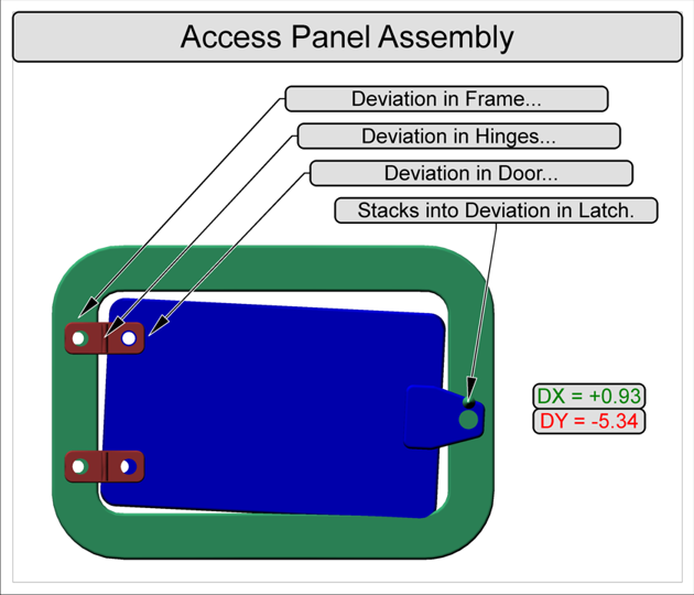
For the Access Panel Assembly scenario shown in the image below, one goal is to predict the deviation measurement between a point on the latch of a door and a point on the frame. The challenge of performing this calculation is that these two points are influenced throughout the assembly process by the deviations of the different components of the access panel assembly.
For example, the Frame has holes on the left side for the two Hinge attachments, and one point on the right that controls where the Latch connects with the door. If there is any deviation in these points on the frame, the attachment of the Latch is going to be affected. Likewise, any resulting deviation in the Hinges will affect how the Door attaches to the Hinges, and so on until the last piece is added to the assembly. These deviations can all add up to an access panel that does not fit properly.
Stacked Alignments are selected via the Edit Subroutines dialog.