Topic Contents: Hide
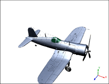
When images are loaded into CM4Di, they are loaded in the background. This means that if a large image is being loaded (requiring a longer load time), you may continue to view your report while the image are yet being loaded. The image below represents what would be seen in the View display when an image is being loaded. The wire box illustrates the "bounding box" or the outermost sides of the image being loaded. While loading an image, you may rotate, zoom, or translate the image.
To edit a View annotation, select the view and then click the Edit View ( ) button on the 3D Toolbar. This allows the View to be edited continuously without resolving until you exit edit mode by clicking the Edit View button again or clicking outside of the View's border.
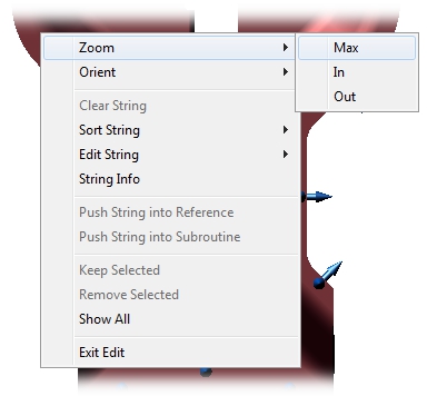
The options available while editing a view include editing or sorting strings and creating or loading Feature sets by right-clicking in the View and selecting the context menu options. Editing a view also allows you to change the visual perspective of a View camera using the Zoom menu options. A 3D image can also be zoomed and/or oriented this way, but unlike wireframe images, 3D images also have the option of using the 3D toolbar to modify perspectives.
If Feature Marker Text is enabled in the view, the text will be displayed while Edit Mode is active. To enable or disable Feature Marker Text, you must edit the view in your CM4Di Startup Template.
While in Edit Mode, you can filter the features you want to see on the sheet and in the grids from the View. To filter out unwanted features:
1. Put the View into Edit Mode by clicking () on the 3D Toolbar.
2. Select a string of features by holding Alt and clicking the feature points. Selected feature points will be displayed with the pink wire box around their markers.
3. Right click one of the selected features and choose one of three available options from the menu:
a. Keep Selected - Removes the features that are not selected from the View, Feature Grid, and DataSet Grid.
b. Remove Selected - Removes the selected features from the View, Feature Grid, and DataSet Grid.
c. Show All - Restores all features within the View, which are then also restored to the Feature Grid and DataSet Grid.
Any image within a View may be rotated to any custom orientation using the Rotate ( ) tool. A View does not have to be in Edit Mode in order to be rotated. However, if it is not, the View will be resolved each time the mouse is released after rotating the image. If a View is in Edit Mode, it will only be resolved once when you Exit. Once a View has been rotated as desired, the orientation may then be saved as a Camera.
1. Click the Edit View () button from the toolbar to enter Edit Mode.
2. Using the Rotate tool, click on the area of the image you would like to rotate and drag the cursor in the desired direction.
A View does not have to be in Edit Mode in order to be rotated. However, if it is not, the View will be resolved each time the mouse is released after rotating the image. If a View is in Edit Mode, it will only be resolved once when you Exit.
You can orient a view to six axis orientations (XY, YX, YZ, ZY, XZ, ZX), or to a user defined isometric perspective. The orientation of a view can be selected by putting the View into Edit mode and using the Orient context menu, or by opening the Camera dialog from the toolbar using the Camera ( ) button and selecting a System Camera from the list.
The Orient context menu consists of the six system-defined camera orientations, as well as the Isometric orientation option.
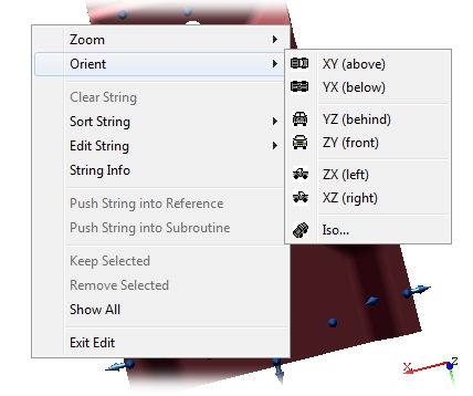
Below are descriptions and examples of each of the seven options available in the Orient context menu of a view:

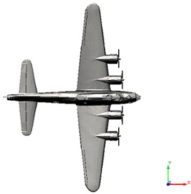
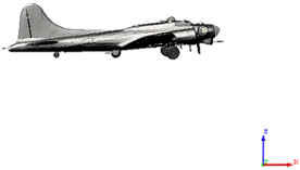
Displays the current image model and features in an XY orientation.

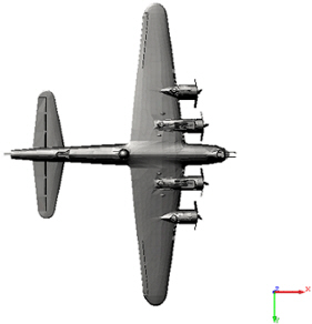
Displays the current image model and features in an YX orientation.

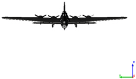
Displays the current image model and features in an YZ orientation.

Displays the current image model and features in an ZY orientation.
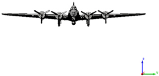

Displays the current image model and features in an ZX orientation.
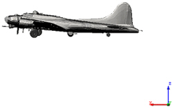

Displays the current image model and features in an XZ orientation.

Displays the current image model and features in an Isometric orientation. Select the desired three dimensional perspective using the radio buttons and click OK.

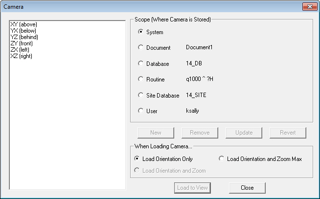
A Camera is a stored orientation of a view. The Camera dialog contains options for storing a views orientation using six Scopes (i.e. places where a Camera may be stored) of system and user-defined cameras:
· System: System cameras are predefined and cannot be modified or deleted. These six cameras incorporate the six basic orientations of a 3D model: XY, YX, YZ, ZY, XZ, and ZX.
· Document: A Document camera is saved with the CM4D document it is created in. Each time that document is opened, regardless of the user, the document camera will be listed for use.
· Database: A Database camera will be saved within the Database to which the document the camera was created in was connected to. Any document connected to that Database will have access to that camera, regardless of the user.
· Routine: A Routine camera will be saved with the Routine to which the View's DataSource is connected to which was selected when the camera was created. Any document or user may access a Routine camera when connected to that specific Routine in a Database.
· Site Database: A Site Database camera will be saved to the Site level. Only users with access to that Site Database will have access to or be allowed to create a Site Database camera. If you are not using a Site Database, this option will not be enabled.
· User: A User camera will be saved with the logged on user information, i.e., a User camera created by JSmith may only be accessed by JSmith in any document.
If you are using Authentication, your Database Privileges will affect which Camera Scopes will be enabled. For example, a user without Document Manager privileges will not be allowed to create or remove Cameras.
1. To save a Camera, orient your View as desired using the OpenGL 3D Toolbar, and then open the Camera () dialog.
2. Select one of the radio buttons within the Scope section.
3. Click New and enter the label you wish to assign to your Camera in the New Label dialog.
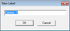
4. Click OK.
5. In order to save your new Camera, you must click Update. If you close the Camera dialog without clicking Update, your new Camera will not be saved.
6. Update your changes to the Database by right-clicking the DataSource icon in the Tree bar and selecting Update to Database from the context menu, or Save your document.
1. To delete a Camera, open the Camera () dialog.
2. Highlight the label of the Camera you wish to delete, and click the Remove button.
3. In order to save your change, you must now click the Update button. If you close the Camera dialog without doing this, your Camera will not be deleted.
4. Update your changes to the Database by right-clicking the DataSource icon in the Tree bar and selecting Update to Database from the context menu, or Save your document.
1. To Load a saved Camera to a current View, select the View on the Sheet and click the Camera button to open the dialog.
2. Select the Scope where the desired Camera exists and highlight the Camera's label from the list box.
3. Select one of the When Loading Camera... radio buttons:
a. Load Orientation Only will retain the Zoom state which the View is currently in, while loading the selected orientation.
b. Load Orientation and Zoom will load not only the saved orientation, but also the Zoomed state the View was in when the Camera was created. This option is only available with user-defined cameras.
c. Load Orientation and Zoom Max will load the saved orientation, the Zoomed stat the View was in when the Camera was created, and maximize the zoom.
4. Click the Load to View button to return to your View and apply the selected Camera and Load options.
To Zoom a View using the OpenGL tools, select the view you wish to zoom. To enable the continuous editing capability on the View (i.e it will only be resolved once when you Exit), select the View and put it into Edit mode by clicking the Edit View () button on the toolbar.
The Zoom state of a View may be saved as a Camera along with the orientation.