Actual Feature Mode is a method for defining if the feature markers in a view represent Actual data . It may be used as an alternative to Spectrum.
The Actual Feature Mode only supports SMI Holes and SMI Slots feature types, and only Polar and Diameter characteristics.
Before setting up Feature Mode to use Actuals, here are some things to keep in mind:
· Feature Mode - Actual requires that the View has a DataSet as its DataSource
· The DataSet must have the "Out of Tolerance" event set
· The feature marker shape and color cannot be modified
· The feature characteristic and number of samples used will determine which feature marker shape will be displayed
· Holes and Slots will appear the same way when using Feature Mode - Actuals
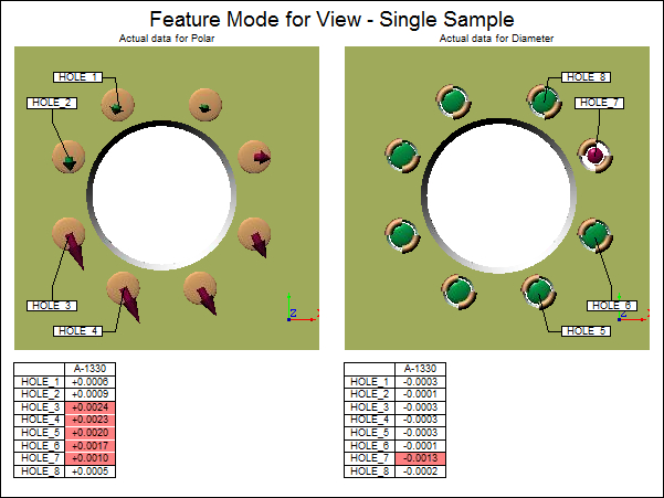
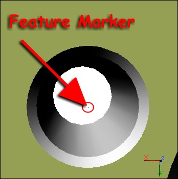
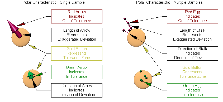
Single sample polar characteristics are represented using an arrow-shaped marker, either green or red (depending on its tolerance state). If the "Display Limit Marker" is enabled in the Feature Mode Setup dialog, then the gold button will appear from the center of the hole to mark the tolerance zone.
A blue marker indicates that the characteristic does not have a tolerance.
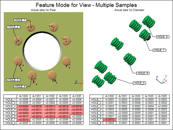
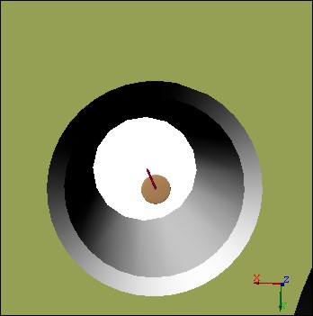
When you have multiple samples, the feature markers are represented with an egg-shaped marker at the end of a stalk.
|
|
|
|
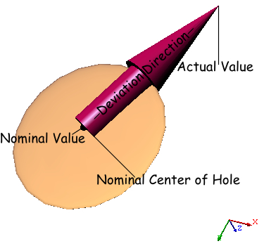
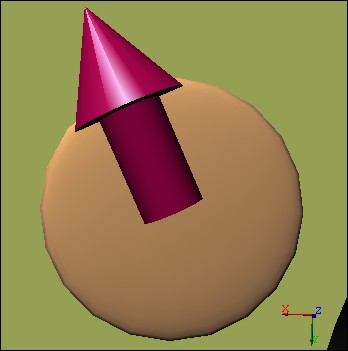
· Base of Arrow - Nominal center of Hole |
|
|
· Tip of Arrow - Actual Value |
|
|
· Arrow Direction - Direction of Deviation |
|
|
· Tolerance Band - Nominal Value is located in the center of the Tolerance Band |
|
To get Polar Features to display in Actual Mode, the data must have:
1. Properly defined SMI Hole Features (“View Features in Grid” to check)
2. Nominal Polar value (set to 0.0)
3. Upper Unilateral Tolerance (you may use upper and lower bilateral if you wish)
4. Actual XYZ values (measurement data)
Once you have the correct Polar data in your database, set up your CM4D document as follows:
1. Create a DataSet
a. Set the DataSource
i. Select Query
ii. All Features
iii. All Samples
b. Set Sift Rules appropriate to diameter data
i. SMI Hole
ii. Polar characteristic to “dev”
c. Set the Event type to “OutOfTolerance”
2. Create a View
a. Set DataSource to the DataSet in step 1
b. Set the View property “Feature Mode” to “Actual”
c. Set the Feature Mode Settings (“Setup” button)
i. Set Exaggeration Factor for Polar to 500
ii. Turned on Display Limit Marker
iii. Set Marker Width to 30
iv. Set Arrow Length to 75
v. Set Arrow Width to 150
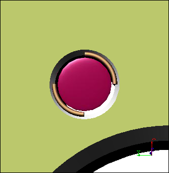
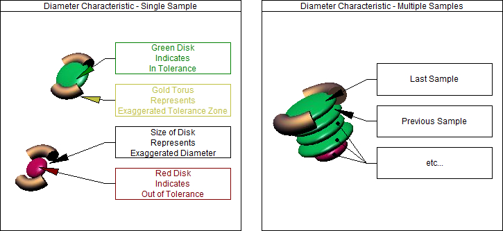
Single sample diameter characteristics are represented using a disk-shaped marker, either green or red (depending on its tolerance state). If the "Display Limit Marker" is enabled in the Feature Mode Setup dialog, then the gold torus will appear around the edge of the disk to mark the tolerance zone.
A blue marker indicates that the characteristic does not have a tolerance.
Feature Mode will only show disks for the current process.
When you have multiple samples, the disks will be "stacked", with the latest sample will be the one with the gold torus with it. After the latest, samples will progress backwards in time.
To get Diameter Features to display in Actual Mode, the data must have:
1. Properly defined SMI Hole Features (“View Features in Grid” to check)
2. Nominal Diameter value
3. Upper and Lower Tolerances
4. Actual Diameter values (measurement data)
Once you have the Diameter data in your database, set up your CM4D document as follows:
1. Create a DataSet
a. Set the DataSource
i. Select Query
ii. All Features
iii. All Samples
b. Set Sift Rules appropriate to diameter data
i. SMI Hole
ii. Diameter characteristic to “dev”
c. Set the Event type to “OutOfTolerance”
2. Create a View
a. Set DataSource to the DataSet in step 1
b. Set the View property “Feature Mode” to “Actual”
c. Set the Feature Mode Settings (“Setup” button)
i. Set Exaggeration Factor for Diameter to 20
ii. Set Exaggeration Factor for Tolerance to 30
iii. Set Marker Width to 17
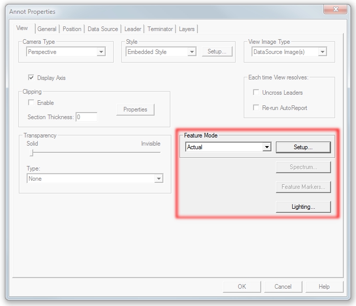
In the View Annot properties dialog, the Feature Mode section is located on the bottom right portion, above the Spectrum, Feature Marker, and Lighting buttons. To access the Feature Mode Setup options, select Actual from the dropdown menu and then click the Setup button located directly above the Spectrum button.
· When Feature Mode is set to Actual, the Spectrum and Feature Marker buttons will be disabled, since they cannot be used together.
· When Feature Mode is set to Nominal, only the Setup button will be disabled.
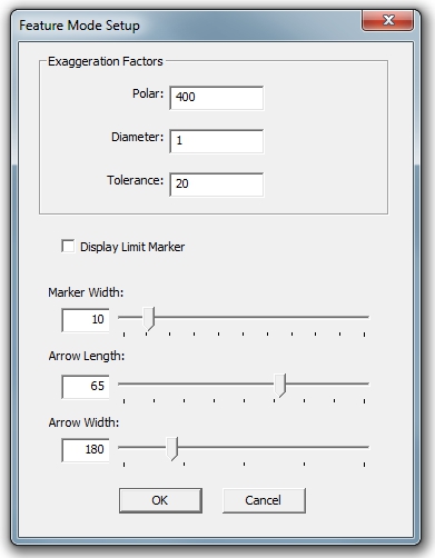
The Feature Mode Setup dialog contains all available values for customizing how your feature markers will be displayed when using Feature Mode.
|
Dialog |
Option |
Description |
|
|
Exaggeration Factors |
Factors entered here are multiplied by the deviation. These factors affect the feature markers and the tolerance band size. |
|
Polar - Used with the Polar characteristic. |
||
|
Diameter - Used with the Diameter characteristic. |
||
|
Tolerance - Used with the Diameter characteristic. |
||
|
Display Limit Marker |
The Limit Marker represents the Tolerance Zone, shown as either a "Gold Button" (for Polar) or a "Gold Torus" (for Diameter). |
|
|
Marker Width |
Increases or decreases the overall size of the feature marker and tolerance zone marker. |
|
|
Arrow Length |
Increases or decreases the length of the arrow head when a feature marker is a Polar characteristic with a single sample. |
|
|
Arrow Width |
Increases or decreases the width of the arrow head when a feature marker is a Polar characteristic with a single sample. |
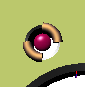
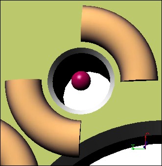
Exaggeration Factors for Polar Characteristic - Single Sample
|
Polar - 1 Display Limit Marker - Enabled Marker Width - 1 Arrow Length - 10 Arrow Width - 100
|
Polar - 50 Display Limit Marker - Enabled Marker Width - 2 Arrow Length - 20 Arrow Width - 150
|
Polar - 400 Display Limit Marker - Enabled Marker Width - 10 Arrow Length - 50 Arrow Width - 200
|
Exaggeration Factors for Diameter Characteristic - Single Sample
|
Diameter - 1 Tolerance - 50 Display Limit Marker - Enabled Marker Width - 5
|
Diameter - 1 Tolerance - 200 Display Limit Marker - Enabled Marker Width - 10
|
Diameter - 2 Tolerance - 400 Display Limit Marker - Enabled Marker Width - 10
|