Peruse 3D Viewer Camera
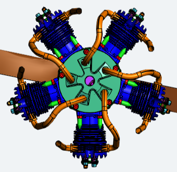
The Viewer Camera tools provide preset camera options to quickly move the model to a specific orientation based on 3D coordinates.
|
|
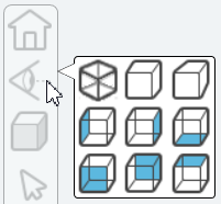
To change the rendering, open the display mode fly-out menu and select one of the nine options:
|
 |
 |
 |
 |
 |
 |
 |
 |
Camera Tools
| Name | Icon | Description |
| Iso View |  |
Isometric view orients the model so the angles between the XYZ axes are equal. |
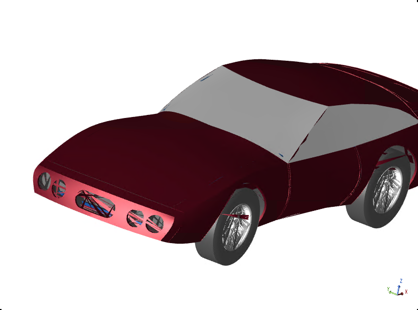
| Orthographic Projection |  |
This projection displays the view in a fixed depth. The model does not scale X and Y coordinates depending on the Z coordinate so the direction of the projection is perpendicular to the camera target plane. |
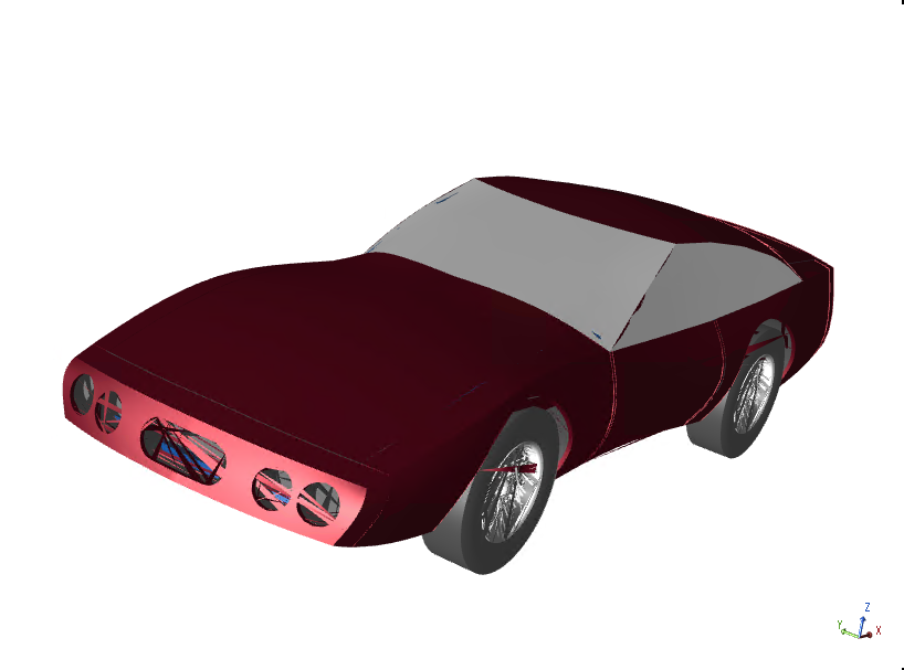
| Perspective Projection |  |
This projection displays the view with depth. The model scales the X and Y coordinates depending on the Z coordinate (depth) so objects that are further away appear smaller on the screen. |
| Left View |  |
Orients the model to view the left side (ZX). |
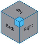
| Right View |  |
Orients the model to view the right side (XZ). |
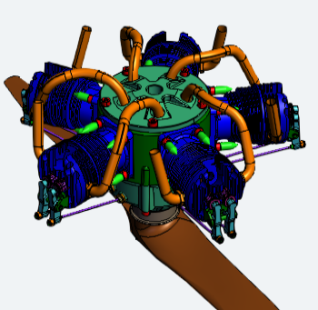
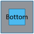
| Bottom View |  |
Orients the model to view the bottom (YX). |
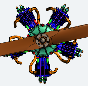
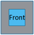
| Front View |  |
Orients the model to view the front (ZY). |
| Back View |  |
Orients the model to view the back (YZ). |
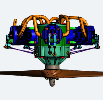
| Top View |  |
Orients the model to view the top (XY). |
Perspective vs. Orthographic
There are two ways to show the model in the 3D Viewer area:
 |
|
|
|
|
|
Perspective |
Orthographic |
Can we improve this topic?