Introduction
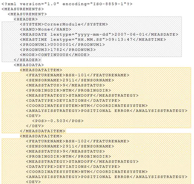
The "CornerModule" data files are *.xml files. The configuration created to read that type of data allows both the Nominal and Actual data files to be read into the database at the same time using a single configuration.
DataSmith concepts demonstrated:
One translator for Nominals and Actuals
Config Extensions
To complete this tutorial:
Download the data file here. Save the zip file and extract the files.
Run DataSmith.
Create a new translator file.
Follow steps 1-6 below.
When you are finished, compare your result with the screen shots shown in the Review section at the end of this topic.
Step 1 - Getting Started
Create a new Config.
Modify the Config properties.
Change the Label to "CornerMod".
Enter the text ”xml” into the Extensions field.
Leave all other options with the default settings.
Click OK.
Save the translator file as "Corner Module Tutorial.4Datasmith". Save periodically from this point onward to avoid losing your progress as you make changes to the translator.
Select
“Add Files” from the “File” menu or click ( ) on the
toolbar.
) on the
toolbar.
Select and open the files CornerModule.xml and CornerModule_U03001.xml.
Step 2 - Define the Header
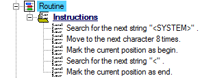
Locate the Instructions node under the Header node.
Define the instructions as:
Search for > next > string > <HEADER>
Mark > current position as begin
Search for > next > string > </HEADER>
Move to > next > character > 9 times
Mark > current position as end
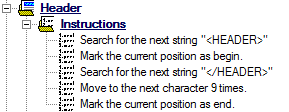
The file should now look like this:
Step 3 - Define a Feature
Locate the node labeled “Feature A” under the Features node.
Double-click "Feature A".
In the Feature Properties dialog:
Change the feature label to “MEASDATAITEM”.
Change the color if desired.
Click Ok.
Locate the Instructions node under "My Feature".
Define the instructions as:
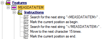
The file should now look like this:
Step 4 - Define Header Characteristics
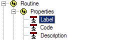
Routine Label
Locate the Characteristics node under the Header node.
Right-click on the Characteristics node
Select New Characteristic from the context menu.
Locate the node labeled “Characteristic A” under the Characteristics node.
Double-click "Characteristic A".
In the Characteristic Properties dialog:
Change the label to “Routine”.
Change the color if desired.
Click Associate.
Select the association Routine>Properties>Label.
Click Ok.
Click Ok.
Locate the Instructions node under "My Routine Label".
Define the instructions as:
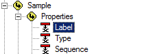
Sample Label
Duplicate the characteristic "Routine".
Open the Characteristic Properties for "Routine (1)".
Change the label to “Sample”.
Change the color if desired.
Click Associate.
Select the association Sample>Properties>Label.
Click Ok.
Click Ok.
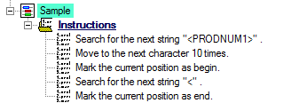
Locate the Instructions node under "Sample".
Change the first instruction string from “<SYSTEM>” to “<PRODNUM1>”.
Change the third instruction from “8 times to 10 times”.
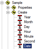
Date
Duplicate the characteristic "Sample".
Open the Characteristic Properties for "Sample (1)".
Change the label to “Date”.
Change the color if desired.
Click Associate.
Select the association Sample>Properties>Label.
Click Ok.
Click Ok.
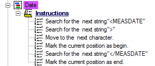
Locate the Instructions node under "Date".
Change the first instruction string from “<PRODNUM1>” to “<MEASDATE”.
Right-click on the second instruction and select New Instruction.
Set the new instruction to "Search for the next strain ">".
Change the third instruction to “Move to the next character”.
Change the fifth instruction from “<” to “</MEASDATE”.
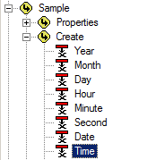
Time
Duplicate the characteristic "Date".
Open the Characteristic Properties for "Date (1)".
Change the label to “Time”.
Change the color if desired.
Click Associate.
Select the association Sample>Properties>Label.
Click Ok.
Click Ok.
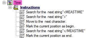
Locate the Instructions node under "Time".
Change the first instruction string from “<MEASDATE” to “<MEASTIME”.
Change the fifth instruction from “</MEASDATE” to “</MEASTIME”.
The file should now look like this:
Step 5 - Define Feature Characteristics
Feature Label
Locate the Characteristics node under the “Features” node.
Right-click on the Characteristics node.
Select New Characteristic from the context menu.
Locate the node labeled “Characteristic A” under the Characteristics node.
Double-click “Characteristic A”.
In the Characteristic Properties dialog:
Change the characteristic label to “Feature Label”.
Change the color if desired.
Click Associate.
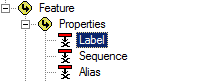
Select the association Feature>Properties>Label.
Click Ok.
Click Ok.
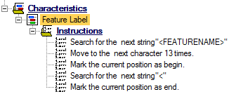
Locate the Instructions node under "Feature Label".
Define the feature instructions as:
Nom X
Locate the Characteristics node under the “Features” node.
Right-click on the Characteristics node.
Select New Characteristic from the context menu.
Locate the node labeled “Characteristic A” under the Characteristics node.
Double-click “Characteristic A”.
In the Characteristic Properties dialog:
Change the characteristic label to “Nom X”.
Change the color if desired.
Click Associate.
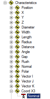
Select the association Feature>Characteristics>Coord X3>Nominal.
Click Ok.
Click Ok.
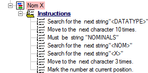
Locate the Instructions node under "Feature Label".
Define the feature instructions as:
Nom Pos
Locate the node “Nom X” that was created in the previous step.
Right-click “Nom X”.
Select Duplicate Characteristic from the context menu.
Double-click "Nom X (1)".
In the Characteristic Properties dialog:
Change the label from “Nom X (1)” to “Nom Pos”
Change the color if desired.
Click Associate.
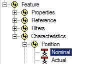
Select the association Feature>Characteristics>Position>Nominal.
Click Ok.
Click Ok.
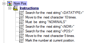
Locate the Instructions node under "Nom Pos".
- rh-list_start class="Numbered" level="2" style="list-style: rh-list; list-style: rh-list;" ?>
Change the fifth instruction from “<X>” to “<POS>”.
Change the sixth instructions from “3 times” to “5 times”.
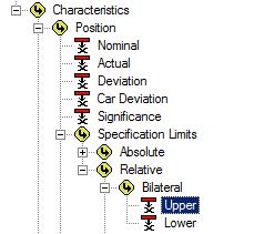
Pos UT
Locate the node “Nom Pos” that was created in the previous step.
Right-click “Nom Pos”.
Select Duplicate Characteristic from the context menu.
Double-click "Nom Pos (1)".
In the Characteristic Properties dialog:
Change the label from “Nom Pos (1)” to “Pos UT”.
Change the color if desired.
Click Associate.
Select the association Feature>Characteristics>Specification Limits>Relative>Bilateral>Upper.
Click Ok.
Click Ok.
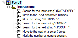
Locate the Instructions node under "Pos UT".
Change the fifth instruction from “<POS>” to “<POSUT>”.
Change the sixth instructions from “5 times” to “7 times”.
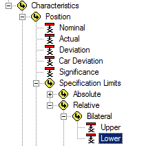
Pos LT
Locate the node “Pos UT” that was created in the previous step.
Right-click “Pos UT”.
Select Duplicate Characteristic from the context menu.
Double-click "Pos UT (1)".
In the Characteristic Properties dialog:
Change the label from “Pos UT (1)” to “Pos LT”.
Change the color if desired.
Click Associate.
Select the association Feature>Characteristics>Specification Limits>Relative>Bilateral>Lower.
Click Ok.
Click Ok.
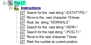
Locate the Instructions node under "Pos LT".
Change the fifth instruction from “<POSUT>” to “<POSLT>”.
Dev Y
Locate the node “Pos LT” that was created in the previous step.
Right-click “Pos LT”.
Select Duplicate Characteristic from the context menu.
Double-click "Pos LT (1)".
In the Characteristic Properties dialog:
Change the label from “Pos LT (1)” to “Dev Y”.
Change the color if desired.
Click Associate.
Select the association Feature>Characteristics>Coord Y3>Nominal.
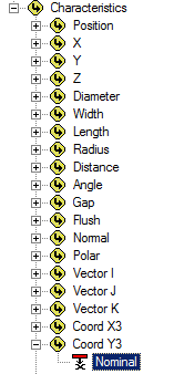
Click Ok.
Click Ok.
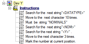
Locate the Instructions node under "Dev Y".
Change the fifth instruction from “<POSLT>” to “<Y>”.
Change the sixth instructions from “7 times” to “3 times”.
Dev Z
Locate the node “Dev Y” that was created in the previous step.
Right-click “Dev Y”.
Select Duplicate Characteristic from the context menu.
Double-click "Dev Y (1)".
In the Characteristic Properties dialog:
Change the label from “Dev Y (1)” to “Dev Z”.
Change the color if desired.
Click Associate.
Select the association Feature>Characteristics>Coord Z3>Nominal.
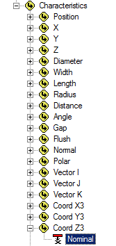
Click Ok.
Click Ok.
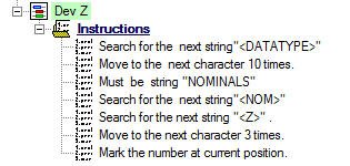
Locate the Instructions node under "Dev Z".
Change the fifth instruction from “<Y>” to “<Z>”.
Dev Pos
Locate the node “Dev Z” that was created in the previous step.
Right-click “Dev Z”.
Select Duplicate Characteristic from the context menu.
Double-click "Dev Z (1)".
In the Characteristic Properties dialog:
Change the label from “Dev Z (1)” to “Dev Pos”.
Change the color if desired.
Click Associate.
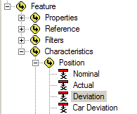
Select the association Feature>Characteristics>Position>Deviation.
Click Ok.
Click Ok.
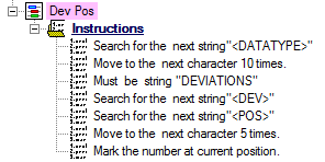
Locate the Instructions node under "Dev Pos".
Change the third instruction from “NOMINALS” to “DEVIATIONS”.
Change the fourth instruction from “<NOM>” to “<DEV>”
Change the fifth instruction from “<Z>” to “<POS>”
Change the sixth instruction from “3 times” to “5 times”
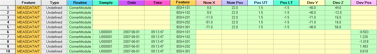
Review Results
Below are screen captures of what the file highlighting and the grid in DataSmith will look like once all of the steps have been completed for the CornerModule configuration. Compare the screen captures to your finished results to confirm that all of the steps were completed successfully.
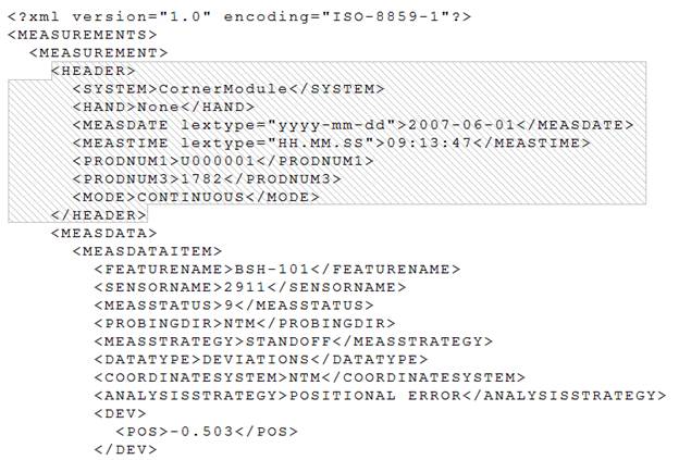
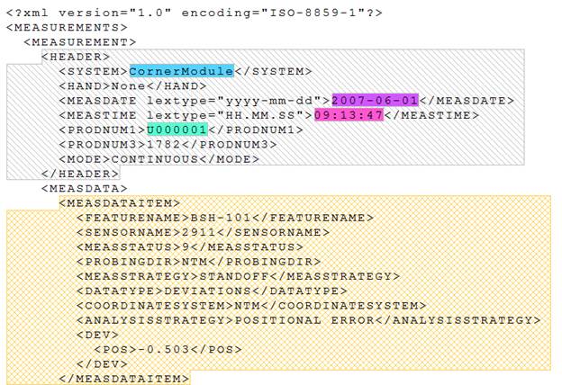
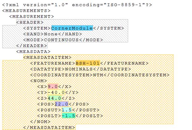
The CornerModule.xml file should now look like this:
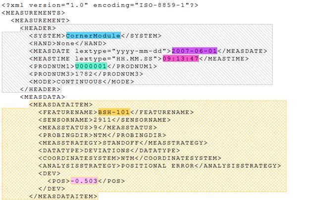
The other *.xml file should now look like this:
Switch the main window the Grid tab. The grid should look like this: