Introduction
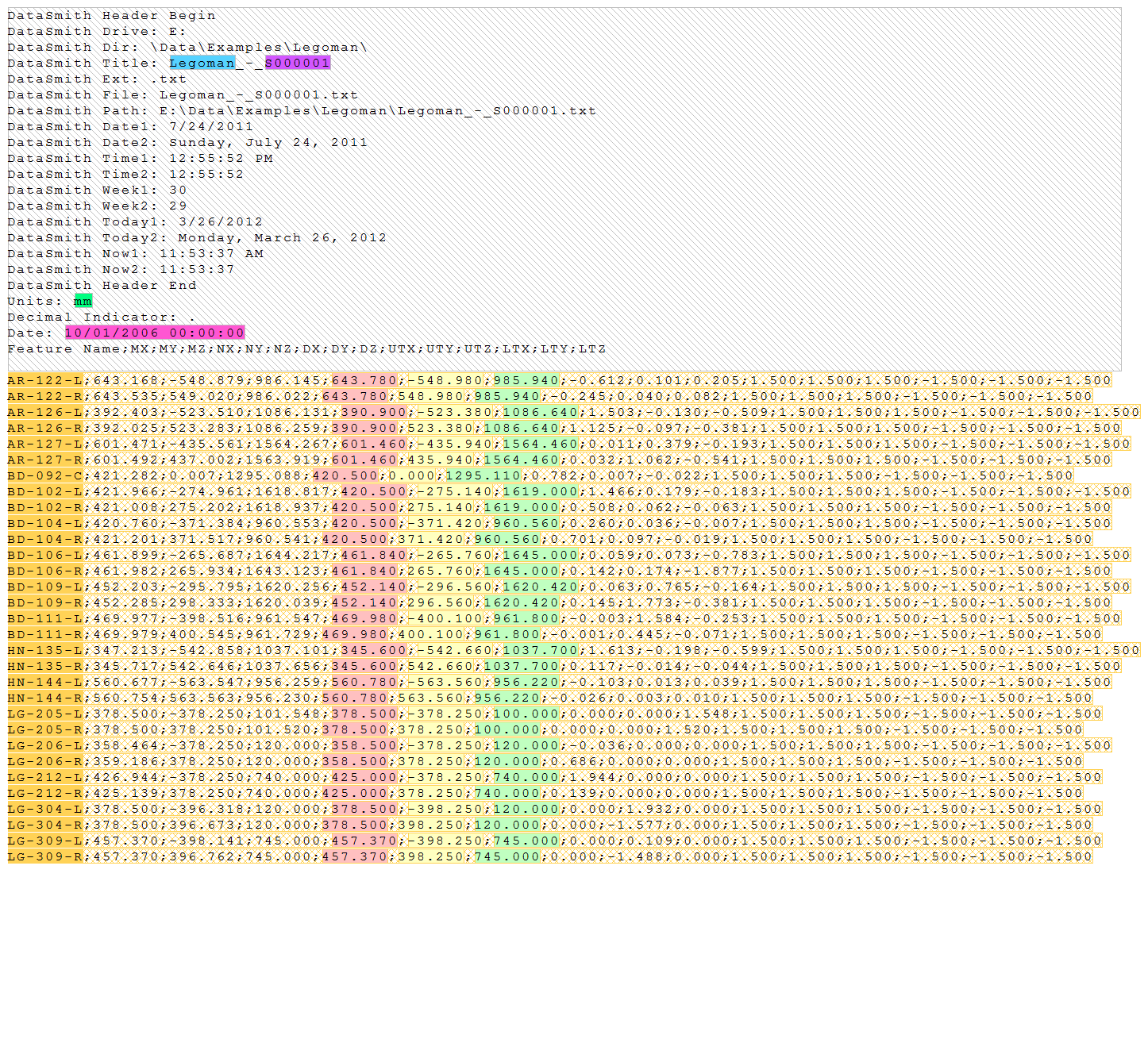
The "LegoMan" data files are *.txt files based on the format of data exported by a CAM2 Q measurement device. The configuration created to read that type of data allows all nominal and measurement data to be read into the database at the same time using a single configuration.
DataSmith concepts demonstrated:
Single Configuration
To complete this tutorial:
Download the data files here. Save the zip file and extract the files.
Run DataSmith.
Create a new translator file.
Follow steps below.
When you are finished, compare your result with the screen shots shown in the Review section at the end of this topic.
Step 1: Getting Started
Right-click the top node of the Configurations tree (labeled with the DataSmith document name).
Select New Config from the context menu.
Step 2: Modify the Config
Locate the new Config on the “Configurations” tree
Should be at the bottom
Likely called “Config A”
Double-click on the config label “Config A”
In the Modify Config dialog:
Change the config label to “Legoman”.
Enter the text “txt” into the Extensions field.
Check “Insert Header” in the Preprocess section.
Click Ok.
From this step onward, all nodes referred to will be located within the "Legoman" config.
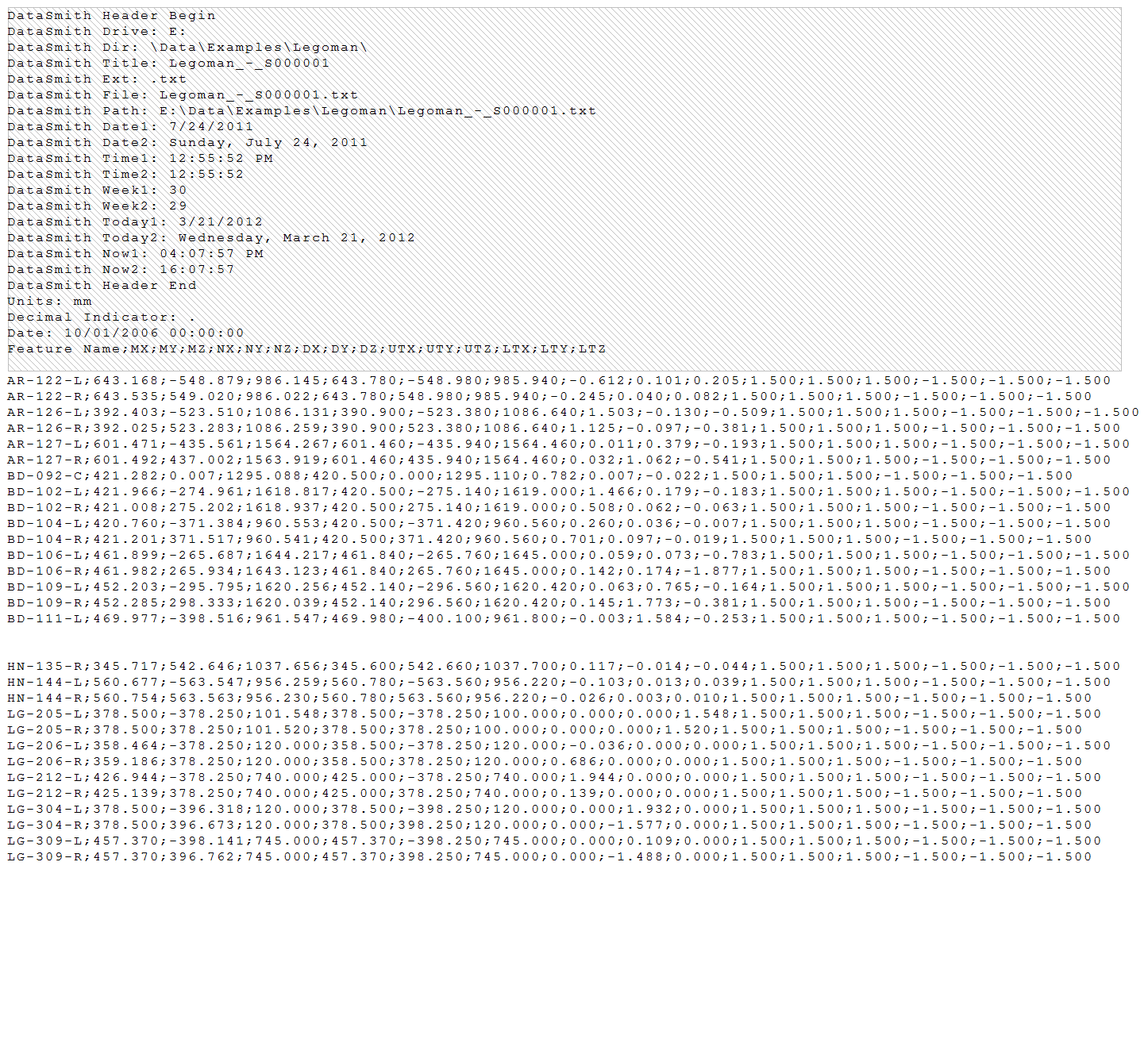
Step 3: Load a File
Make sure the config you just created is selected in the tree.
Select Add Files from the File menu or click the Add Files toolbar button.
Browse to the folder containing the Legoman translator.
Select and open the “Legoman_-_S000001.txt” file.
The raw file will be displayed in the main window area.
Step 4: Define the Header
Locate the Instructions node under the Header node.
Define the instructions as:
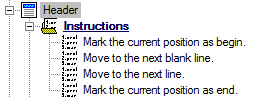
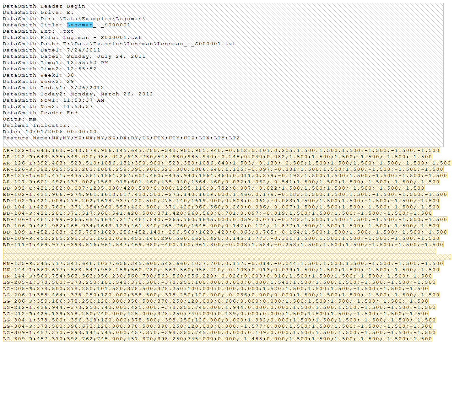
The file should now look like this:
 Show/Hide
ScreenshotShow/Hide
Screenshot
Show/Hide
ScreenshotShow/Hide
Screenshot
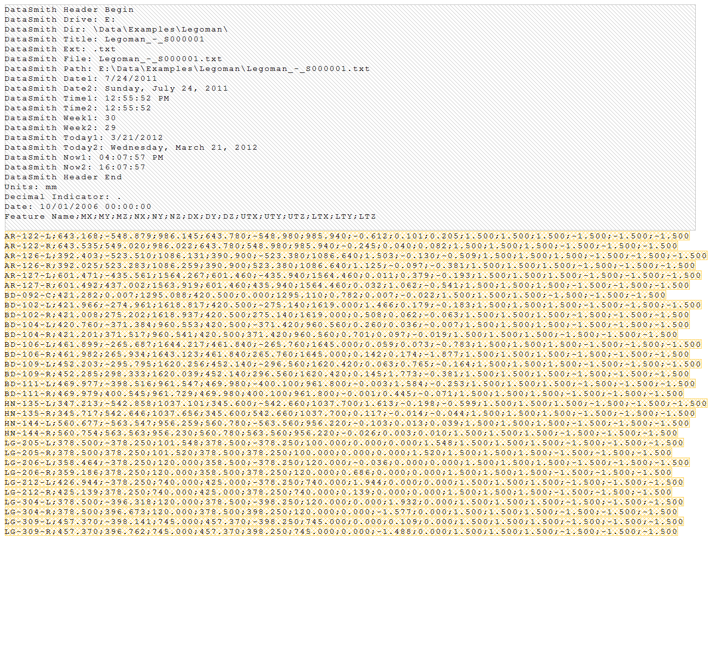
Step 5: Define a Feature
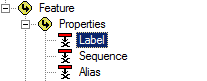
Locate the node labeled “Feature A” under the Features node.
Double-click "Feature A".
In the Feature Properties dialog:
Change the feature label to “Feature”.
Change the color to Light Orange.
Click Ok.
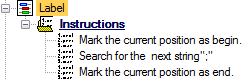
Locate the Instructions node under "Feature".
Define the instructions as:
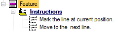
The file should now look like this:
Show/Hide
ScreenshotShow/Hide
Screenshot
Step 6: Define Header Characteristics
Locate the Characteristics node under the Header node.
Right-click on the Characteristics node
Select New Characteristic from the context menu.
Locate the node labeled “Characteristic A” under the Characteristics node.
Double-click "Characteristic A".
In the Characteristic Properties dialog:
Change the label to “Routine (file name)”.
Change the color to Light Blueberry.
Click Associate.
In the Associations dialog:
Select the association Routine>Properties>Label.
 Show/Hide
ScreenshotShow/Hide
Screenshot
Show/Hide
ScreenshotShow/Hide
Screenshot

Click Ok.
Click Ok.
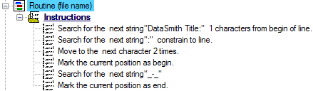
Locate the Instructions node under "Routine (file name)".
Define the instructions as:
The file should now look like this:
Show/Hide ScreenshotShow/Hide Screenshot
Duplicate the characteristic "Routine (file name)".
Open the Characteristic Properties.
Change the characteristic label to “Sample (file name)”.
Change the color to Light Grape.
Click Associate.
In the Associations dialog:
Change the association to Sample>Properties>Label.
Show/Hide
ScreenshotShow/Hide
Screenshot
Click Ok.
Click Ok.
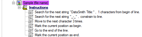
Locate the Instructions node under "Sample (file name)".
Change the second instruction string from “:” to “_-_”
Change the third instruction from “2 times to 3 times”
Change the fifth instruction to “Go to the end of line.”
Duplicate the characteristic "Sample(file name)".
Open the Characteristic Properties.
Change the characteristic label to “Date”.
Change the color to Light Strawberry.
Click Associate.
In the Associations dialog:
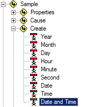
Change the association to Sample>Create>Date and Time.
Show/Hide
ScreenshotShow/Hide
Screenshot
Click Ok.
Set the Type Validation to "DateTime (date and time)".
Click Ok.
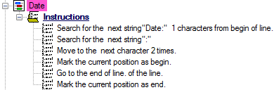
Locate the Instructions node under "Date".
Change the first instruction string from “DataSmith Title:” to “Date:”
Change the second instruction string from “_-_” to “:”
Change the third instruction from “3 times” to “2 times” and remove “constrain to line”
Duplicate the characteristic "Date".
Open the Characteristic Properties.
Change the characteristic label to “Units”.
Change the color to Avocado.
Click Associate.
In the Associations dialog:
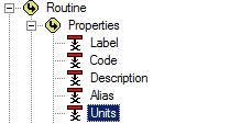
Change the association to Routine>Properties>Units.
Show/Hide
ScreenshotShow/Hide
Screenshot
Click Ok.
Click Mangle.
Select the “Make Lower Case” check box.
Select the “Lookup” radio button.
In the ‘Change this:’ box, enter the text “mm”.
Hit the return key and enter the text “in”.
In the ‘To this:’ box, enter the text “1”.
Hit the return key and enter the text “2”.
 Show/Hide
ScreenshotShow/Hide
Screenshot
Show/Hide
ScreenshotShow/Hide
Screenshot

Click Ok.
Set the Type Validation to "Text".
Click Ok.
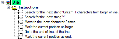
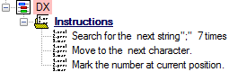
Locate the Instructions node under "Units".
Change the first instruction string from “Date:” to “Units:”
The file should now look like this:
Show/Hide
ScreenshotShow/Hide
Screenshot
Step 7: Define Feature Characteristics - Feature Label
Locate the Characteristics node under the “Feature” node.
Right-click on the Characteristics node.
Select New Characteristic from the context menu.
Locate the node labeled “Characteristic A” under the Characteristics node.
Double-click “Characteristic A”.
In the Characteristic Properties dialog:
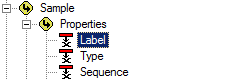
Change the characteristic label to “Label”.
Change the color to Light Orange.
Click Associate.
In the Associations dialog:
Select the association Feature>Properties>Label.
Show/Hide
ScreenshotShow/Hide
Screenshot
Click Ok.
Click Ok.
Locate the Instructions node under "Label".
Define the instructions as:
Note that the search string is a semi-colon, not a colon.
The file should now look like this:
Show/Hide
ScreenshotShow/Hide
Screenshot
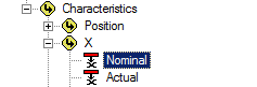
Step 8: Define Feature Characteristics - Nominal (XYZ)
Locate the Characteristics node under the “Feature” node.
Right-click on the Characteristics node.
Select New Characteristic from the context menu.
Locate the node labeled “Characteristic A” under the Characteristics node.
Double-click “Characteristic A”.
In the Characteristic Properties dialog:
Change the characteristic label to “NX”.
Change the color to Light Red.
Click Associate.
In the Associations dialog:
Select the association Feature>Characteristics>X>Nominal.
Show/Hide
ScreenshotShow/Hide
Screenshot
Click Ok.
Click Mangle.
Select the “Lookup” radio button.
In the ‘Change this:’ box, enter the string “*,*”.
In the ‘To this:’ box, enter the string “**”.
Show/Hide
ScreenshotShow/Hide
Screenshot
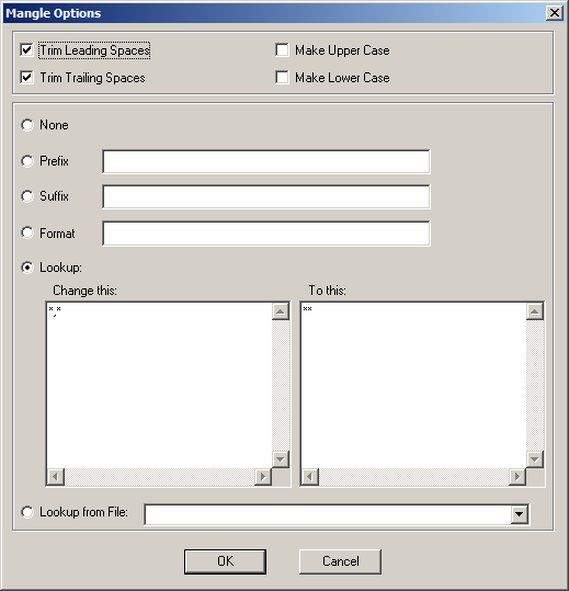
Click Ok.
Set the Type Validation to "Real (decimal value)".
Click Ok.
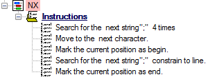
Locate the Instructions node under "NX".
Define the instructions as:
Duplicate the "NX" Characteristic.
Double-click “NX (1)”.
In the Characteristic Properties dialog:
Change the characteristic label to “NY".
Change the color to Light Yellow.
Click Associate.
In the Associations dialog:
Select the association Feature>Characteristics>Y>Nominal.
Show/Hide
ScreenshotShow/Hide
Screenshot
Click Ok.
Click Ok.
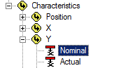
Locate the Instructions node under "NY".
Change the first search instruction from “4 times” to “5 times”.
Duplicate the "NY" Characteristic.
Double-click “NY (1)”.
In the Characteristic Properties dialog:
Change the characteristic label to “NZ".
Change the color to Light Green.
Click Associate.
In the Associations dialog:
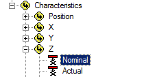
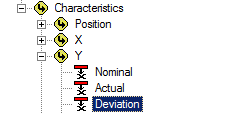
Select the association Feature>Characteristics>Z>Nominal.
Show/Hide
ScreenshotShow/Hide
Screenshot
Click Ok.
Click Ok.
Locate the Instructions node under "NZ".
Change the first search instruction from “5 times” to “6 times".
The file should now look like this:
Show/Hide
ScreenshotShow/Hide
Screenshot
Step 9: Define Feature Characteristics - Deviations (XYZ)
Duplicate the "NZ" Characteristic that was created in Step 8.
Double-click “NZ (1)”.
In the Characteristic Properties dialog:
Change the characteristic label to “DX".
Change the color to Light Red.
Click Associate.
In the Associations dialog:
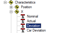
Select the association Feature>Characteristics>X>Deviation.
Show/Hide
ScreenshotShow/Hide
Screenshot
Click Ok.
Set the Type Validation to "Real (decimal value)".
Click Ok.
Locate the Instructions node under "DX".
Define the instructions as:
Duplicate the "DX" Characteristic.
Double-click “DX (1)”.
In the Characteristic Properties dialog:
Change the characteristic label to “DY".
Change the color to Light Yellow.
Click Associate.
In the Associations dialog:
Select the association Feature>Characteristics>Y>Deviation.
Show/Hide
ScreenshotShow/Hide
Screenshot
Click Ok.
Click Ok.
Locate the Instructions node under "DY".
Change the first search instruction from “7 times” to “8 times".
Duplicate the "DY" Characteristic.
Double-click “DY (1)”.
In the Characteristic Properties dialog:
Change the characteristic label to “DZ".
Change the color to Light Green.
Click Associate.
In the Associations dialog:
Select the association Feature>Characteristics>Z>Deviation.
Show/Hide
ScreenshotShow/Hide
Screenshot
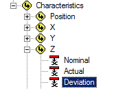
Click Ok.
Click Ok.
Locate the Instructions node under "DZ".
Change the first search instruction from “8 times” to “9 times".
The file should now look like this:
Show/Hide
ScreenshotShow/Hide
Screenshot
Step 10: Define Feature Characteristics - Upper Spec Limits (XYZ)
Duplicate the "DZ" Characteristic that was created in Step 9.
Double-click “DZ (1)”.
In the Characteristic Properties dialog:
Change the characteristic label to “UX".
Change the color to Strawberry.
Click Associate.
In the Associations dialog:
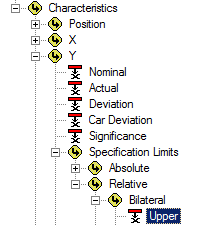
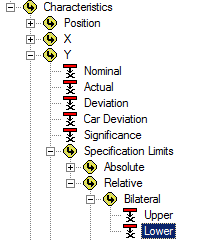
Select the association Feature>Characteristics>X>Specification Limits>Relative>Bilateral>Upper.
Show/Hide
ScreenshotShow/Hide
Screenshot
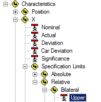
Click Ok.
Click Ok.
Locate the Instructions node under "UX".
Change the first search instruction from “9 times” to “10 times”.
Duplicate the "UX" Characteristic.
Double-click “UX (1)”.
In the Characteristic Properties dialog:
Change the characteristic label to “UY".
Change the color to Orange.
Click Associate.
In the Associations dialog:
Select the association Feature>Characteristics>Y>Specification Limits>Relative>Bilateral>Upper.
Show/Hide
ScreenshotShow/Hide
Screenshot
Click Ok.
Click Ok.
Locate the Instructions node under "UY".
Change the first search instruction from “10 times” to “11 times”.
Duplicate the "UY" Characteristic.
Double-click “UY (1)”.
In the Characteristic Properties dialog:
Change the characteristic label to “UZ".
Change the color to Lime.
Click Associate.
In the Associations dialog:
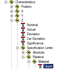
Select the association Feature>Characteristics>Z>Specification Limits>Relative>Bilateral>Upper.
Show/Hide
ScreenshotShow/Hide
Screenshot
Click Ok.
Click Ok.
Locate the Instructions node under "UZ".
Define the instructions as:
Change the first search instruction from “11 times” to “12 times".
The file should now look like this:
Show/Hide
ScreenshotShow/Hide
Screenshot
Step 11: Define Feature Characteristics – Lower Spec Limits (XYZ)
Duplicate the "UZ" Characteristic that was created in Step 9.
Double-click “UZ (1)”.
In the Characteristic Properties dialog:
Change the characteristic label to “LX".
Change the color to Light Strawberry.
Click Associate.
In the Associations dialog:
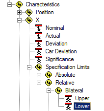
Select the association Feature>Characteristics>X>Specification Limits>Relative>Bilateral>Lower.
Show/Hide
ScreenshotShow/Hide
Screenshot
Click Ok.
Click Ok.
Locate the Instructions node under "LX".
Change the first search instruction from “12 times” to “13 times”.
Duplicate the "LX" Characteristic.
Double-click “LX (1)”.
In the Characteristic Properties dialog:
Change the characteristic label to “LY".
Change the color to Light Orange.
Click Associate.
In the Associations dialog:
Select the association Feature>Characteristics>Y>Specification Limits>Relative>Bilateral>Lower.
Show/Hide
ScreenshotShow/Hide
Screenshot
Click Ok.
Click Ok.
Locate the Instructions node under "LY".
Change the first search instruction from “13 times” to “14 times”.
Duplicate the "LY" Characteristic.
Double-click “LY (1)”.
In the Characteristic Properties dialog:
Change the characteristic label to “LZ".
Change the color to Light Lime.
Click Associate.
In the Associations dialog:
Select the association Feature>Characteristics>Z>Specification Limits>Relative>Bilateral>Lower.
Show/Hide
ScreenshotShow/Hide
Screenshot
Click Ok.
Click Ok.
Locate the Instructions node under "LZ".
Define the instructions as:
Change the first search instruction from “14 times” to “15 times".
The file should now look like this:
Show/Hide
ScreenshotShow/Hide
Screenshot
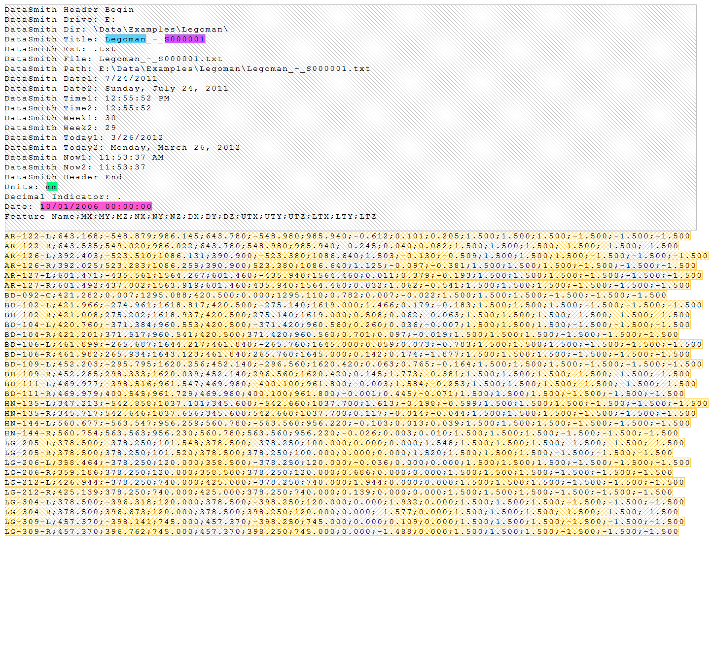
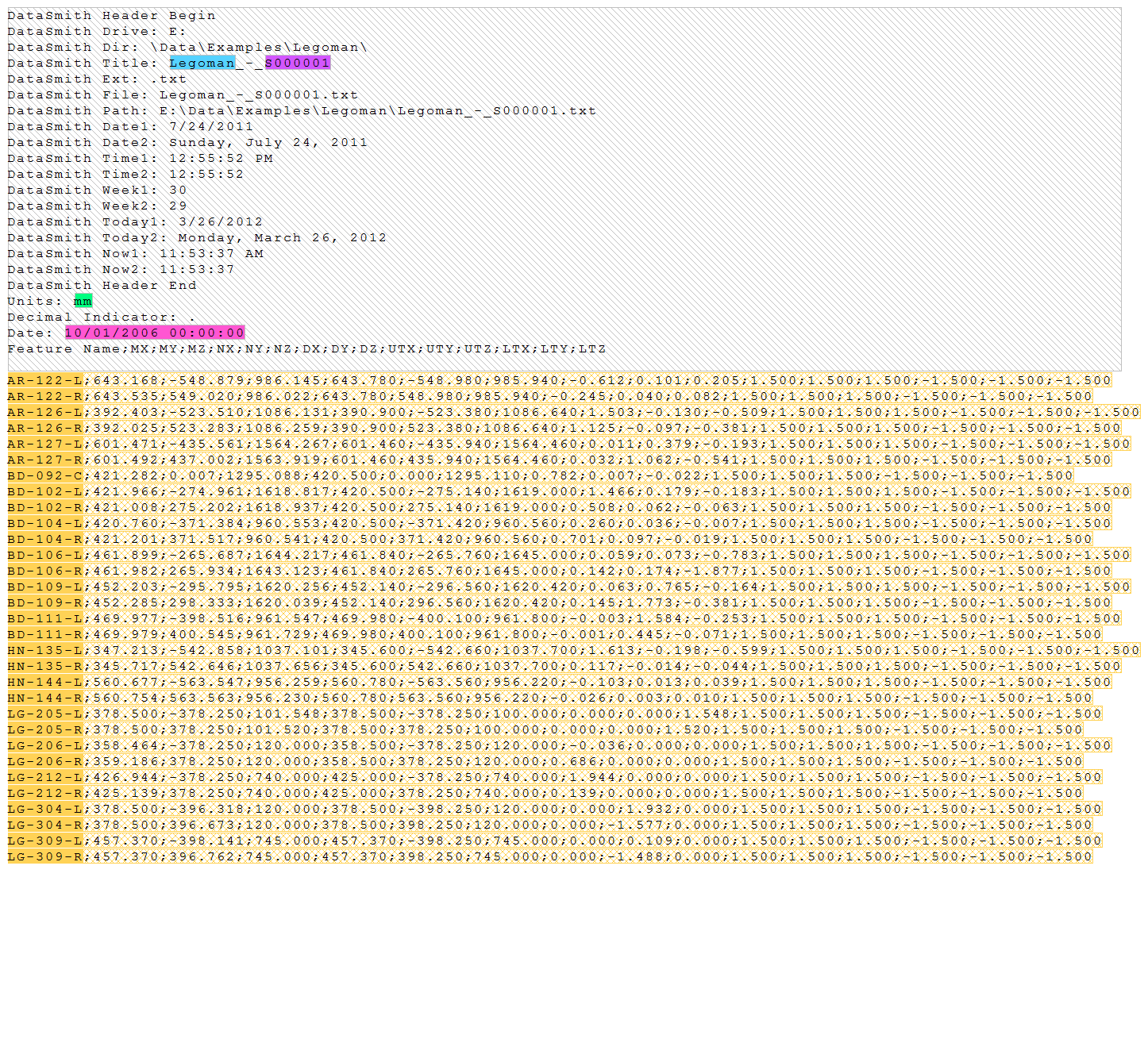
Step 12: Review Results
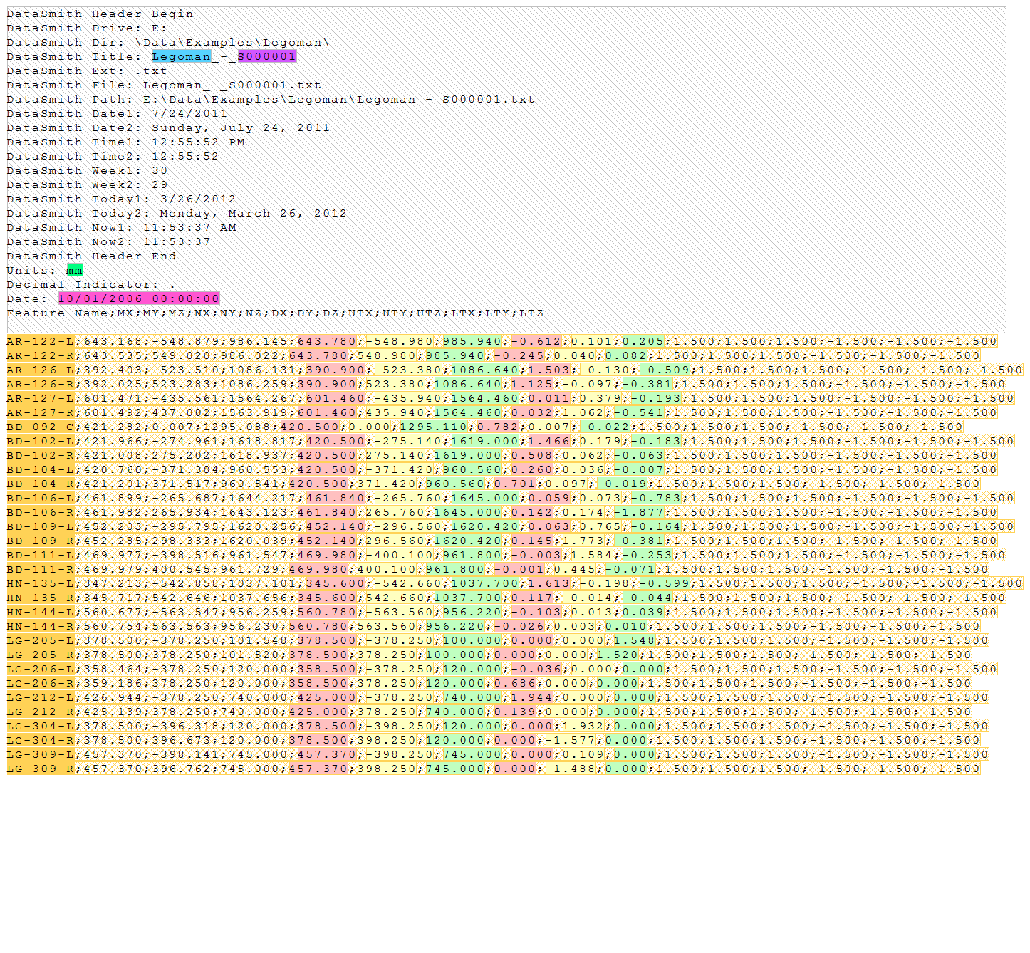
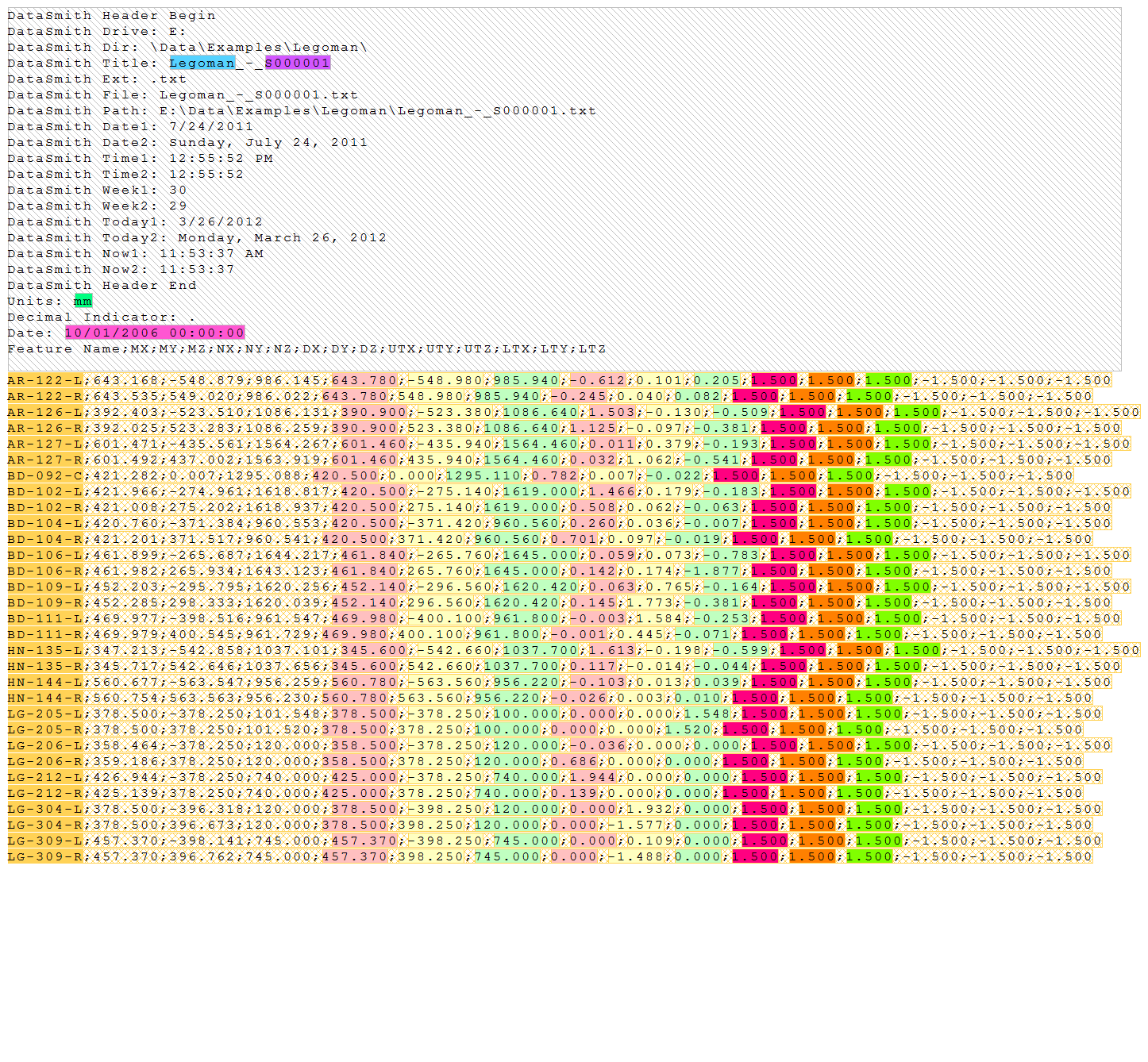
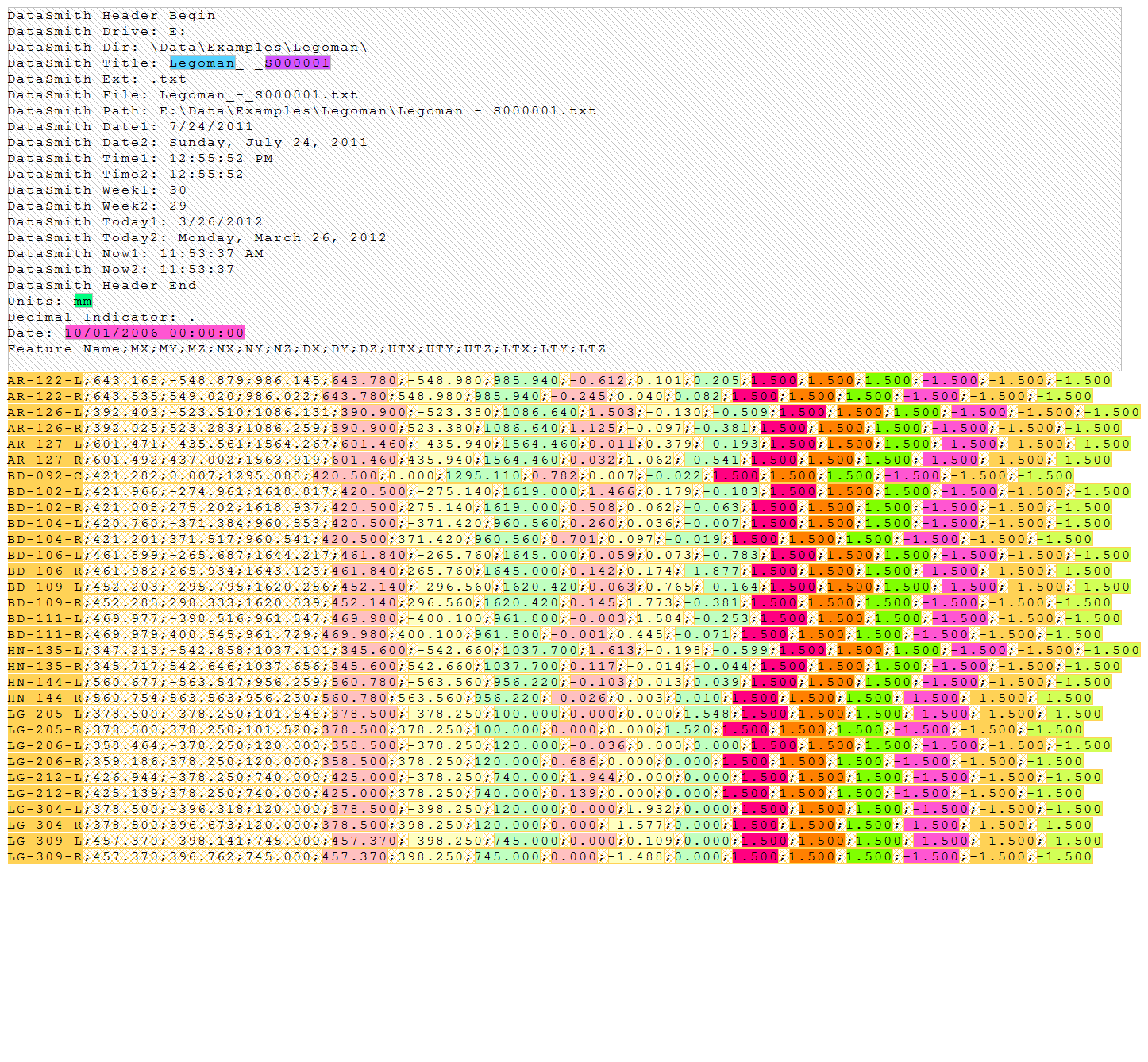
Below are screen captures of what the file highlighting and the grid in DataSmith will look like once all of the steps have been completed for the Legoman configuration. Compare the screen captures to your finished results to confirm that all of the steps were completed successfully.
The file should now look like this:
Show/Hide
ScreenshotShow/Hide
Screenshot

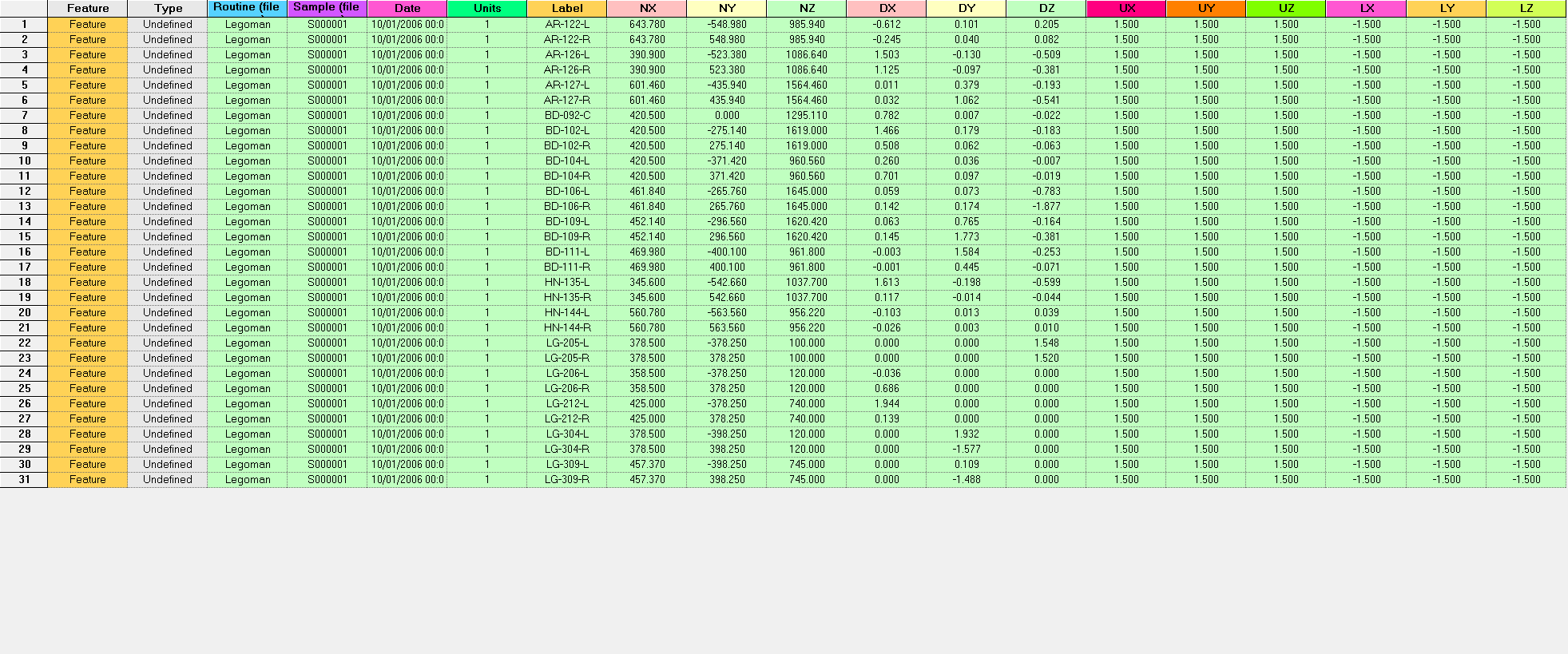
Switch the main window from the Legoman_-_S000001.txt tab to the Grid tab.
The grid should look like this:
Show/Hide
ScreenshotShow/Hide
Screenshot
You have reached the end of the Legoman Tutorial, and are now ready to read the Legoman data files into your Database!