Introduction
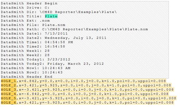
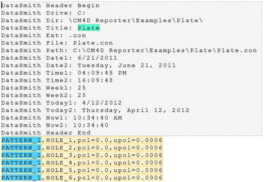
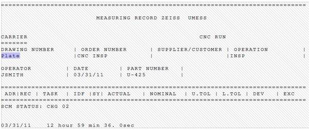
The "Plate" data files are *.XL8 files based on the format of data exported from CMM devices. For this type of data, the Nominal and measurement data is read into the database using multiple configurations, while the constructed features are being created by yet a third configuration. The Plate example shows a translator that is uses three Configs to read data: 1) Nominals, 2) Actuals, and 3) Constructed.
Nominals - Only nominal data files are read into the database using this configuration.
Construction - Creates a CM4D constructed feature from the features entered into the database by the Nominals configuration.
Actuals - Only actual data files are read into the database using this configuration.
DataSmith concepts demonstrated:
Polar Data
Constructed Features
XL8 File Format
All Configs in a single translator
To complete this tutorial:
Download the data files here. Save the zip file and extract the files.
Run DataSmith.
Create a new translator file.
Follow steps below.
When you are finished, compare your result with the screen shots shown in the Review section at the end of this topic.
Plate Nominals Config
Step 1: Getting Started
Right-click the top node of the Configurations tree (labeled with the DataSmith document name).
Select New Config from the context menu.
Step 2: Modify the Config
Locate the new config on the Configurations tree.
New configs are usually added to tree after any other existing configs.
The new config is likely called “Config A”.
Double-click "Config A".
In the Modify Config dialog:
Change the config label to "My Plate Nominals”.
Enter the text ”nom” into the Extensions field.
In the Preprocess group, select the Insert Header check box.
Click Ok.
From this step onward, all nodes referred to will be located within the My Plate Nominals config.
Step 3: Load a File
Make sure the config you just created is selected in the tree.
Select Add Files from the File menu or click the Add Files ( ) toolbar button.
Browse to the folder containing the Plate tutorial.
Select the file Plate.nom file.
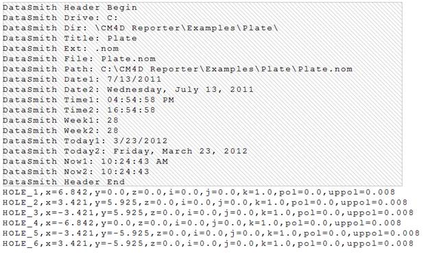
The raw file will be displayed in the main window area.
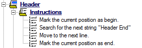
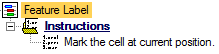
Step 4: Define the Header
Locate the Instructions node under the Header node.
Define the instructions as:
To view a screenshot of the expected results, click the link below:
 Show/Hide ScreenshotShow/Hide Screenshot
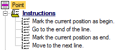
Step 5: Define a Feature
Locate the node labeled “Feature A” under the Features node.
Double-click "Feature A".
In the Feature Properties dialog:
Change the feature label to “Point”.
Change the color if desired.
Click Ok.
Locate the Instructions node under "My Feature".
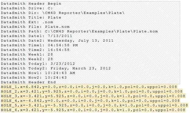
Define the instructions as:
The file should now look like this:
Show/Hide ScreenshotShow/Hide Screenshot
Step 6: Define a Comment
Locate the node labeled “Comment A” under the Comments node
Double-click "Comment A".
In the Comment Properties dialog:
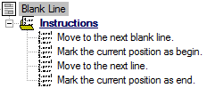
Change the comment label to “Blank Line”
Click Ok.
Locate the Instructions node under "Blank Line".
Define the instructions as:
Step 7: Define Header Characteristics
Locate the Characteristics node under the Header node.
Right-click on the Characteristics node
Select New Characteristic from the context menu.
Locate the node labeled “Characteristic A” under the Characteristics node.
Double-click "Characteristic A".
In the Characteristic Properties dialog:
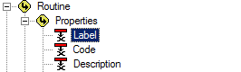
Change the label to “Routine”.
Change the color if desired.
Click Associate.
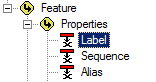
In the Associations dialog:
Select the association Routine>Properties>Label.
Click Ok.
Click Ok.
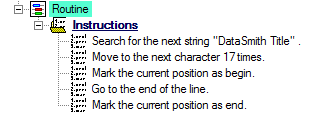
Locate the Instructions node under "My Routine Label".
Define the instructions as:
The file should now look like this:
Show/Hide ScreenshotShow/Hide Screenshot
Step 8: Define Feature Characteristic - Feature Label
Locate the Characteristics node under the “Point” node.
Right-click on the Characteristics node.
Select New Characteristic from the context menu.
Locate the node labeled “Characteristic A” under the Characteristics node.
Double-click “Characteristic A”.
In the Characteristic Properties dialog:
Change the characteristic label to “Feature Label”.
Change the color if desired.
Click Associate.
In the Associations dialog:
Select the association Feature>Properties>Label.
Click Ok.
Click Ok.
Locate the Instructions node under "Feature Label".
Define the feature instructions as:
The file should now look like this:
Show/Hide ScreenshotShow/Hide Screenshot
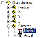
Step 9: Define Feature Characteristic - Nominal Diameter
Locate the Characteristics node under the “Point” node.
Right-click on the Characteristics node.
Select New Characteristic from the context menu.
Locate the node labeled “Characteristic A” under the Characteristics node.
Double-click “Characteristic A”.
In the Characteristic Properties dialog:
Change the characteristic label to “Nom Dia”.
Change the color if desired.
Click Associate.
In the Associations dialog:
Select the association Feature>Characteristics>Diameter>Nominal.
Click Ok.
From the Type Validation dropdown, select Real (decimal value).
Click Ok.
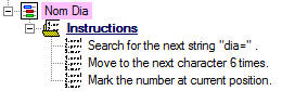
Locate the Instructions node under "Nom Dia".
Define the feature instructions as:
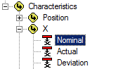
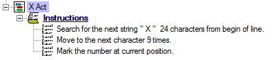
Step 10: Define Feature Characteristic - Nominal X
Locate the node “Nom Dia” that was created in the previous step.
Right-click “Nom Dia”.
Select Duplicate Characteristic from the context menu.
Double-click "Nom Dia (1)".
In the Characteristic Properties dialog:
Change the label from “Nom Dia (1)” to “Nom X”
Change the color if desired.
Click Associate.
In the Associations dialog:
Select the association Feature>Characteristics>X>Nominal.
Click Ok.
Click Ok.
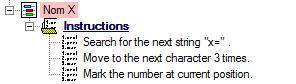
Locate the Instructions node under "Nom X".
Change the first instruction from “dia=” to “x=”.
Change the second instruction from “6 times” to “3 times”.
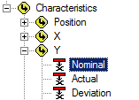
Step 11: Define Feature Characteristic - Nominal Y
Locate the node “Nom X” that was created in the previous step.
Right-click “Nom X”.
Select Duplicate Characteristic from the context menu.
Double-click "Nom X (1)".
In the Characteristic Properties dialog:
Change the label from “Nom X (1)” to “Nom Y”
Change the color if desired.
Click Associate.
In the Associations dialog:
Select the association Feature>Characteristics>Y>Nominal.
Click Ok.
Click Ok.
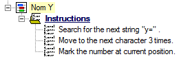
Locate the Instructions node under "Nom Y".
Change the first instruction from “x=” to “y=”.
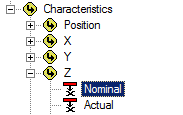
Step 12: Define Feature Characteristic - Nominal Z
Locate the node “Nom Y” that was created in the previous step.
Right-click “Nom Y”.
Select Duplicate Characteristic from the context menu.
Double-click "Nom Y (1)".
In the Characteristic Properties dialog:
Change the label from “Nom Y (1)” to “Nom Z”
Change the color if desired.
Click Associate.
In the Associations dialog:
Select the association Feature>Characteristics>Z>Nominal.
Click Ok.
Click Ok.
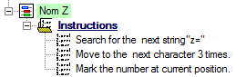
Locate the Instructions node under "Nom Z".
Change the first instruction from “y=” to “z=”.
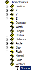
Step 13: Define Feature Characteristic - Nominal I
Locate the node “Nom Z” that was created in the previous step.
Right-click “Nom Z”.
Select Duplicate Characteristic from the context menu.
Double-click "Nom Z (1)".
In the Characteristic Properties dialog:
Change the label from “Nom Z (1)” to “Nom I”
Change the color if desired.
Click Associate.
In the Associations dialog:
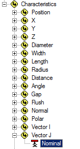
Select the association Feature>Characteristics>Vector I>Nominal.
Click Ok.
Click Ok.
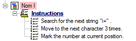
Locate the Instructions node under "Nom I".
Change the first instruction from “z=” to “i=”.
Step 14: Define Feature Characteristic - Nominal J
Locate the node “Nom I” that was created in the previous step.
Right-click “Nom I”.
Select Duplicate Characteristic from the context menu.
Double-click "Nom I (1)".
In the Characteristic Properties dialog:
Change the label from “Nom I (1)” to “Nom J”
Change the color if desired.
Click Associate.
In the Associations dialog:
Select the association Feature>Characteristics>Vector J>Nominal.
Click Ok.
Click Ok.
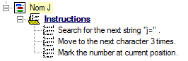
Locate the Instructions node under "Nom J".
Change the first instruction from “i=” to “j=”.
Step 15: Define Feature Characteristic - Nominal K
Locate the node “Nom J” that was created in the previous step.
Right-click “Nom J”.
Select Duplicate Characteristic from the context menu.
Double-click "Nom J (1)".
In the Characteristic Properties dialog:
Change the label from “Nom J (1)” to “Nom K”
Change the color if desired.
Click Associate.
In the Associations dialog:
Select the association Feature>Characteristics>Vector K>Nominal.
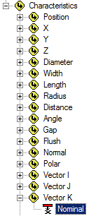
Click Ok.
Click Ok.
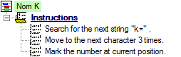
Locate the Instructions node under "Nom K".
Change the first instruction from “j=” to “k=”.
Step 16: Define Feature Characteristic - Upper Diameter
Locate the node “Nom K” that was created in the previous step.
Right-click “Nom K”.
Select Duplicate Characteristic from the context menu.
Double-click "Nom K (1)".
In the Characteristic Properties dialog:
Change the label from “Nom K (1)” to “Upper Dia”
Change the color if desired.
Click Associate.
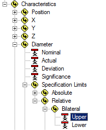
In the Associations dialog:
Select the association Feature>Characteristics>Diameter>Specification Limits>Relative>Bilateral>Upper.
Click Ok.
Click Ok.
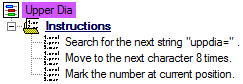
Locate the Instructions node under "Upper Dia".
Change the first instruction from “k=” to “uppdia=”.
Change the second instruction from "3 times" to "8 times".
Step 17: Define Feature Characteristic - Lower Diameter
Locate the node “Upper Dia” that was created in the previous step.
Right-click “Upper Dia”.
Select Duplicate Characteristic from the context menu.
Double-click "Upper Dia (1)".
In the Characteristic Properties dialog:
Change the label from “Upper Dia (1)” to “Lower Dia”
Change the color if desired.
Click Associate.
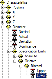
In the Associations dialog:
Select the association Feature>Characteristics>Diameter>Specification Limits>Relative>Bilateral>Lower.
Click Ok.
Click Ok.
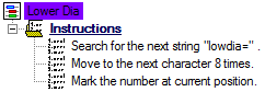
Locate the Instructions node under "Lower Dia".
Change the first instruction from “uppdia=” to “lowdia=”.
Step 18: Define Feature Characteristic - Nominal Polar
Locate the node “Lower Dia” that was created in the previous step.
Right-click “Lower Dia”.
Select Duplicate Characteristic from the context menu.
Double-click "Lower Dia (1)".
In the Characteristic Properties dialog:
Change the label from “Lower Dia (1)” to “Nom Polar”
Change the color if desired.
Click Associate.
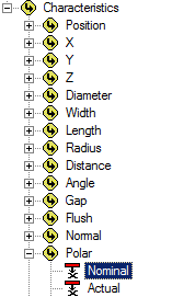
In the Associations dialog:
Select the association Feature>Characteristics>Polar>Nominal.
Click Ok.
Click Ok.
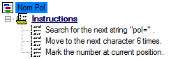
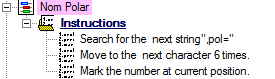
Locate the Instructions node under "Nom Polar".
Change the first instruction from “lowdia=” to “pol=”.
Change the second instruction from "8 times" to "6 times".
Step 19: Define Feature Characteristic - Nominal Position
Locate the node “Nom Polar” that was created in the previous step.
Right-click “Nom Polar”.
Select Duplicate Characteristic from the context menu.
Double-click "Nom Polar (1)".
In the Characteristic Properties dialog:
Change the label from “Nom Polar (1)” to “Nom Pos”
Change the color if desired.
Click Associate.
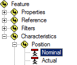
In the Associations dialog:
Select the association Feature>Characteristics>Position>Nominal.
Click Ok.
Click Ok.
Locate the Instructions node under "Nom Pos".
Change the first instruction from “pol=” to “pos=”.
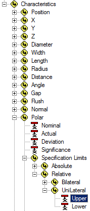
Step 20: Define Feature Characteristic - Upper Polar
Locate the node “Nom Pos” that was created in the previous step.
Right-click “Nom Pos”.
Select Duplicate Characteristic from the context menu.
Double-click "Nom Pos (1)".
In the Characteristic Properties dialog:
Change the label from “Nom Pos (1)” to “Upper Polar”
Change the color if desired.
Click Associate.
In the Associations dialog:
Select the association Feature>Characteristics>Polar>Specification LImits>Relative>UniLateral>Upper.
Click Ok.
Click Ok.
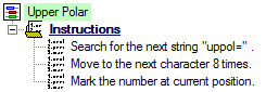
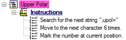
Locate the Instructions node under "Upper Polar".
Change the first instruction from “pos=” to “uppol=”.
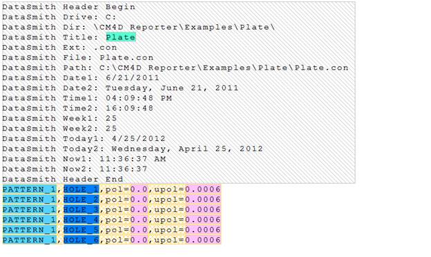
The file should now look like this:
Show/Hide ScreenshotShow/Hide Screenshot
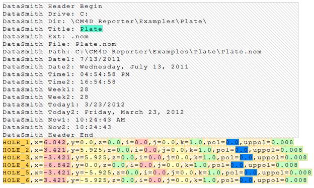
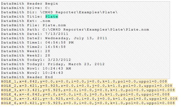
Step 21: Review Results for Plate Nominals
Below are screen captures of what the file highlighting and the grid in DataSmith will look like once all of the steps have been completed for the Plate Nominals configuration. Compare the screen captures to your finished results to confirm that all of the steps were completed successfully.
The file should now look like this:
Show/Hide ScreenshotShow/Hide Screenshot
Switch the main window from the Plate.nom tab to the Grid tab.
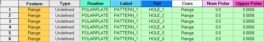
The grid should look like this:
 Show/Hide ScreenshotShow/Hide Screenshot

Once you have completed the first 20 steps, save your DataSmith document and continue on to create the Plate Constructed translator.
Plate Constructed Config
Step 22: Create a Config
Right-click the top node of the Configurations tree (labeled with the DataSmith document name).
Select New Config from the context menu.
Step 23: Modify the Config
Locate the new config on the Configurations tree.
New configs are usually added to tree after any other existing configs.
The new config is likely called “Config A”.
Double-click "Config A".
In the Modify Config dialog:
Change the config label to "My Plate Constructed”.
Enter the text ”con” into the Extensions field.
In the Preprocess group, select the Insert Header check box.
Click Ok.
From this step onward, all nodes referred to will be located within the My Plate Constructed config.
Step 24: Load a File
Make sure the config you just created is selected in the tree.
Select Add Files from the File menu or click the Add Files () toolbar button.
Browse to the folder containing the Plate tutorial.
Select the file Plate.con file.
The raw file will be displayed in the main window area.
Step 25: Define the Header
Locate the Instructions node under the Header node.
Define the instructions as:
To view a screenshot of the expected results, click the link below:
Show/Hide ScreenshotShow/Hide Screenshot
Step 26: Define a Feature
Locate the node labeled “Feature A” under the Features node.
Double-click "Feature A".
In the Feature Properties dialog:
Change the feature label to “Range”.
Change the color if desired.
Click Ok.
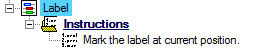
Locate the Instructions node under "My Feature".
Define the instructions as:
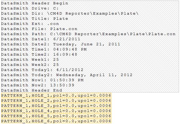
The file should now look like this:
Show/Hide ScreenshotShow/Hide Screenshot
Step 27: Define a Comment
Locate the Comment Characteristic in the "My Plate Nominals" config that you created in the previous steps.
Right-click the “Blank Line” characteristic.
Select Copy Characteristic from the context menu.
Locate the Comments node in the "My Plate Constructed" config.
Right-click the Comments node.
Select Paste Characteristic.
Right-click "Comment A" and select Delete Characteristic.
Step 28: Define Header Characteristics
Locate the Header Characteristics node in the "My Plate Nominals" config.
Right-click the “Routine” characteristic.
Select Copy Characteristic from the context menu.
Locate the Header node in the "My Plate Constructed" config.
Right-click the Characteristics node.
Select Paste Characteristic.
Right-click "Characteristic A" and select Delete Characteristic.
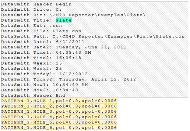
The file should now look like this:
Show/Hide ScreenshotShow/Hide Screenshot
Step 29: Define Feature Characteristic - Label
Locate the Features node in the "My Plate Nominals" config.
Right-click the “Feature Label” characteristic for the "Point" feature.
Select Copy Characteristic from the context menu.
Locate the Features node in the "My Plate Constructed" config.
Right-click "Characteristic A" under the "Range" feature node.
Select Paste Characteristic.
Double-click "Feature Label".
In the Characteristic Properties dialog, change the name of the characteristic to "Label".
Click OK.
The file should now look like this:
Show/Hide ScreenshotShow/Hide Screenshot
Step 30: Define Feature Characteristic - Reference
Locate the node labeled “Characteristic A” under the Characteristics node.
Double-click “Characteristic A”.
In the Characteristic Properties dialog:
Change the characteristic label to “Ref”.
Change the color if desired.
Click Associate.
In the Associations dialog:
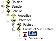
Select the association Feature>Reference>Construct Sub Feature>Label.
Click Ok.
Click Ok.
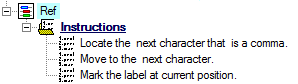
Locate the Instructions node under "Ref".
Define the feature instructions as:
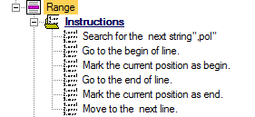
Step 31: Define Feature Characteristic - Polar
Locate the Characteristics node under the “Point” node.
Right-click on the Characteristics node.
Select New Characteristic from the context menu.
Locate the node labeled “Characteristic A” under the Characteristics node.
Double-click “Characteristic A”.
In the Characteristic Properties dialog:
Change the characteristic label to “Cons”.
Change the color if desired.
Click Associate.
In the Associations dialog:
Select the association Feature>Properties>Construct Method>Polar.
Click Ok.
In the Default String field, enter "Polar".
Click Ok.
Step 32: Define Feature Characteristic - Nominal Polar
Locate the Features node in the "My Plate Nominals" config.
Right-click the “Nom Polar” characteristic for the "Point" feature.
Select Copy Characteristic from the context menu.
Locate the Features node in the "My Plate Constructed" config.
Right-click "Characteristics node under the "Range" feature.
Select Paste Characteristic.
If you want to change the color, double-click "Nom Polar" and edit the Characteristics Properties.
Step 33: Define Feature Characteristic - Upper Polar
Locate the Features node in the "My Plate Nominals" config.
Right-click the “Upper Polar” characteristic for the "Point" feature.
Select Copy Characteristic from the context menu.
Locate the Features node in the "My Plate Constructed" config.
Right-click "Characteristics node under the "Range" feature.
Select Paste Characteristic.
If you want to change the color, double-click "Nom Polar" and edit the Characteristics Properties.
Locate the Instructions node under "Upper Polar".
Define the feature instructions as:
Change the first instruction from “uppol=” to “upol=”.
Change the second instruction from "8 times" to "6 times".
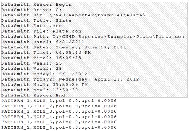
Step 34: Review Results for Plate Constructed
Below are screen captures of what the file highlighting and the grid in DataSmith will look like once all of the steps have been completed for the Plate Constructed configuration. Compare the screen captures to your finished results to confirm that all of the steps were completed successfully.
The file should now look like this:
Show/Hide ScreenshotShow/Hide Screenshot
Switch the main window from the Plate.con tab to the Grid tab.
The grid should look like this:
Show/Hide ScreenshotShow/Hide Screenshot
Once you have completed the first 33 steps, save your DataSmith document and continue on to create the Plate Actuals translator.
Plate Actuals Config
Step 35: Create a Config
Right-click the top node of the Configurations tree (labeled with the DataSmith document name).
Select New Config from the context menu.
Step 36: Modify the Config
Locate the new config on the Configurations tree.
New configs are usually added to tree after any other existing configs.
The new config is likely called “Config A”.
Double-click "Config A".
In the Modify Config dialog:
Change the config label to "My Plate Actuals”.
Enter the text ”rtxt” into the Extensions field.
Click Ok.
From this step onward, all nodes referred to will be located within the My Plate Actuals config.
Step 37: Load a File
Make sure the config you just created is selected in the tree.
Select Add Files from the File menu or click the Add Files () toolbar button.
Browse to the folder containing the Plate tutorial.
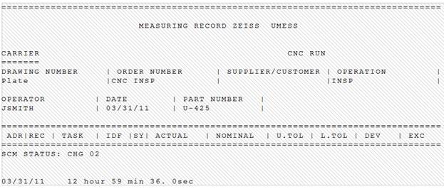
Select the file Plate U-425.rtxt file.
The raw file will be displayed in the main window area.
Step 38: Define the Header
Locate the Instructions node under the Header node.
Define the instructions as:
To view a screenshot of the expected results, click the link below:
 Show/Hide ScreenshotShow/Hide Screenshot
Step 39: Define a Feature
Locate the node labeled “Feature A” under the Features node.
Double-click "Feature A".
In the Feature Properties dialog:
Change the feature label to “NEXT”.
Change the color if desired.
Click Ok.
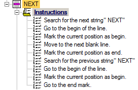
Locate the Instructions node under "My Feature".
Define the instructions as:
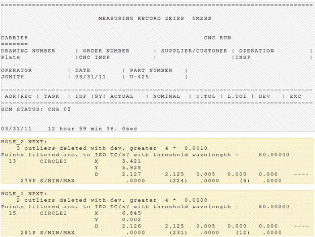
The file should now look like this:
Show/Hide ScreenshotShow/Hide Screenshot
Step 40: Define Header Characteristics
Locate the Characteristics node under the Header node.
Right-click on the Characteristics node
Select New Characteristic from the context menu.
Locate the node labeled “Characteristic A” under the Characteristics node.
Double-click "Characteristic A".
In the Characteristic Properties dialog:
Change the label to “Routine”.
Change the color if desired.
Click Associate.
In the Associations dialog:
Select the association Routine>Properties>Label.
Click Ok.
Click Ok.
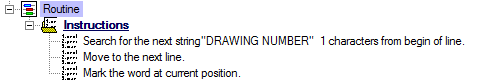
Locate the Instructions node under "My Routine Label".
Define the instructions as:
The file should now look like this:
Show/Hide ScreenshotShow/Hide Screenshot
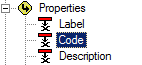
Step 41: Define Header Characteristics - Code
Locate the Characteristics node under the Header node.
Right-click on the Characteristics node
Select New Characteristic from the context menu.
Locate the node labeled “Characteristic A” under the Characteristics node.
Double-click "Characteristic A".
In the Characteristic Properties dialog:
Change the label to “Code”.
Change the color if desired.
Click Associate.
In the Associations dialog:
Select the association Routine>Properties>Code.
Click Ok.
Click Mangle.
In the Mangle dialog:
Select the "Format" radio button.
Enter "~Routine~" in the Format text field.
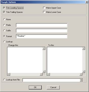
Click OK.
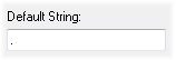
In the Default String field, enter ".".
Click Ok.
Step 42: Define Header Characteristics - Department
Locate the Characteristics node under the Header node.
Right-click on the Characteristics node
Select New Characteristic from the context menu.
Locate the node labeled “Characteristic A” under the Characteristics node.
Double-click "Characteristic A".
In the Characteristic Properties dialog:
Change the label to “Department”.
Change the color if desired.
Click Associate.
In the Associations dialog:
Select the association Routine>Filters>D.
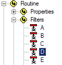
Click Ok.
In the Default String field, enter "Drive Systems".
Click Ok.
Step 43: Define Header Characteristics - Units
Locate the Characteristics node under the Header node.
Right-click on the Characteristics node
Select New Characteristic from the context menu.
Locate the node labeled “Characteristic A” under the Characteristics node.
Double-click "Characteristic A".
In the Characteristic Properties dialog:
Change the label to “Units”.
Change the color if desired.
Click Associate.
In the Associations dialog:
Select the association Routine>Properties>Units.
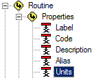
Click Ok.
In the Default String field, enter "2".
Click Ok.
Step 44: Define Header Characteristics - Sample
Locate the Characteristics node under the Header node.
Right-click on the Characteristics node
Select New Characteristic from the context menu.
Locate the node labeled “Characteristic A” under the Characteristics node.
Double-click "Characteristic A".
In the Characteristic Properties dialog:
Change the label to “Sample”.
Change the color if desired.
Click Associate.
In the Associations dialog:
Select the association Sample>Properties>Label.
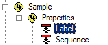
Click Ok.
Click Ok.
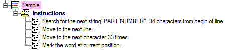
Locate the Instructions node under "Sample".
Define the feature instructions as:
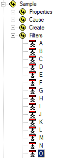
Step 45: Define Header Characteristics - Operator
Locate the Characteristics node under the Header node.
Right-click on the Characteristics node
Select New Characteristic from the context menu.
Locate the node labeled “Characteristic A” under the Characteristics node.
Double-click "Characteristic A".
In the Characteristic Properties dialog:
Change the label to “Operator”.
Change the color if desired.
Click Associate.
In the Associations dialog:
Select the association Sample>Filters>O.
Click Ok.
Click Ok.
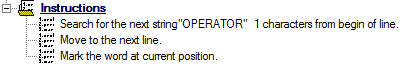
Locate the Instructions node under "Sample".
Define the feature instructions as:
Step 46: Define Header Characteristics - Date
Locate the Characteristics node under the Header node.
Right-click on the Characteristics node
Select New Characteristic from the context menu.
Locate the node labeled “Characteristic A” under the Characteristics node.
Double-click "Characteristic A".
In the Characteristic Properties dialog:
Change the label to “Date”.
Change the color if desired.
From the Type Validation dropdown, select Date (date only).
Click Ok.
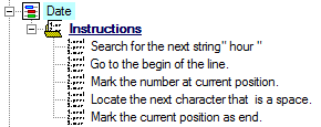
Locate the Instructions node under "Sample".
Define the feature instructions as:
Step 47: Define Header Characteristics - Hour
Locate the Characteristics node under the Header node.
Right-click on the Characteristics node
Select New Characteristic from the context menu.
Locate the node labeled “Characteristic A” under the Characteristics node.
Double-click "Characteristic A".
In the Characteristic Properties dialog:
Change the label to “Hour”.
Change the color if desired.
From the Type Validation dropdown, select Integer (whole number).
Click Ok.
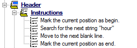
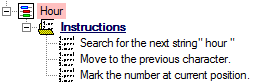
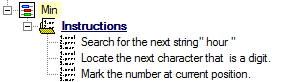
Locate the Instructions node under "Hour".
Define the feature instructions as:
Step 48: Define Header Characteristics - Minute
Locate the node “Hour” that was created in the previous step.
Right-click “Hour”.
Select Duplicate Characteristic from the context menu.
Double-click "Hour (1)".
In the Characteristic Properties dialog:
Change the label from “Hour (1)” to “Min”
Change the color if desired.
Click Ok.
Locate the Instructions node under "Nom Z".
Change the second instruction to "Move to the previous character".
Step 49: Define Header Characteristics - Second
Locate the node “Min” that was created in the previous step.
Right-click “Min”.
Select Duplicate Characteristic from the context menu.
Double-click "Min (1)".
In the Characteristic Properties dialog:
Change the label from “Min (1)” to “Sec”
Change the color if desired.
Click Ok.
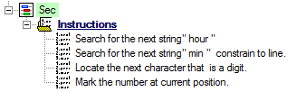
Locate the Instructions node under "Sec".
Right-click the second instruction (Locate) and select "Insert Instruction".
Change the new "Undefined" instruction to "Search for the next string " min " constrain to line.
Step 50: Define Header Characteristics - Date/Time
Locate the Characteristics node under the Header node.
Right-click on the Characteristics node
Select New Characteristic from the context menu.
Locate the node labeled “Characteristic A” under the Characteristics node.
Double-click "Characteristic A".
In the Characteristic Properties dialog:
Change the label to “Date/Time”.
Change the color if desired.
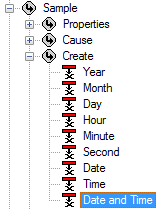
Click Associate.
In the Associations dialog:
Select the association Sample>Create>Date and Time.
Click Ok.
Click Ok.
Click Mangle.
In the Mangle dialog:
Select the "Format" radio button.
Enter "~Date~ ~Hour~:~Min~:~Sec~" in the Format text field.
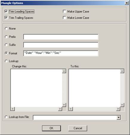
Click OK.
From the Type Validation dropdown, select Date Time (date and time).
In the Default String field, enter "<mangled>".
Click Ok.
Step 51: Define Feature Characteristic - Label
Locate the Characteristics node under the “Point” node.
Right-click on the Characteristics node.
Select New Characteristic from the context menu.
Locate the node labeled “Characteristic A” under the Characteristics node.
Double-click “Characteristic A”.
In the Characteristic Properties dialog:
Change the characteristic label to “Label”.
Change the color if desired.
Click Associate.
In the Associations dialog:
Select the association Feature>Properties>Label.
Click Ok.
Click Ok.
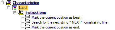
Locate the Instructions node under "Label".
Define the feature instructions as:
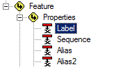
Step 52: Define Feature Characteristic - Sequence
Locate the node “Label” that was created in the previous step.
Right-click “Label”.
Select Duplicate Characteristic from the context menu.
Double-click "Label (1)".
In the Characteristic Properties dialog:
Change the label from “Label (1)” to “Seq”
Change the color if desired.
Click Associate.
In the Associations dialog:
Change the association from Label to Sequence.
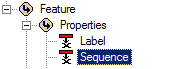
Click Ok.
Click Mangle.
In the Mangle dialog:
Select the "Format" radio button.
Enter "~ord~" in the Format text field.
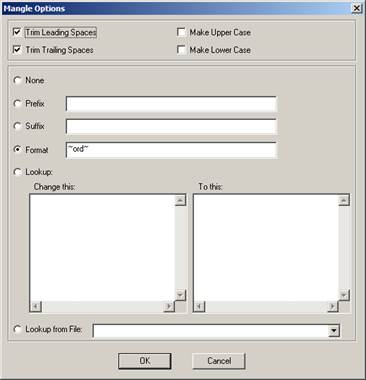
Click OK.
In the Default String field, enter "<mangled>".
Click OK.
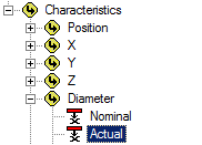
Step 53: Define Feature Characteristic - Diameter Actual
Locate the Characteristics node under the “Point” node.
Right-click on the Characteristics node.
Select New Characteristic from the context menu.
Locate the node labeled “Characteristic A” under the Characteristics node.
Double-click “Characteristic A”.
In the Characteristic Properties dialog:
Change the characteristic label to “D Act”.
Change the color if desired.
Click Associate.
In the Associations dialog:
Select the association Feature>Characteristics>Diameter>Actual.
Click Ok.
From the Type Validation dropdown menu, select Real (decimal value).
Click Ok.
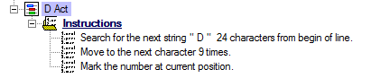
Locate the Instructions node under "D Act".
Define the feature instructions as:
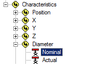
Step 54: Define Feature Characteristic - Diameter Nominal
Locate the node “D Act” that was created in the previous step.
Right-click “D Act”.
Select Duplicate Characteristic from the context menu.
Double-click "D Act (1)".
In the Characteristic Properties dialog:
Change the label from “D Act (1)” to “D Nom”
Change the color if desired.
Click Associate.
In the Associations dialog:
Select the association Feature>Characteristics>Diameter>Nominal.
Click Ok.
Click Ok.
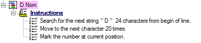
Locate the Instructions node under "D Nom".
Define the feature instructions as:
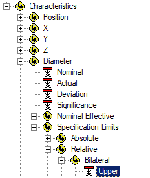
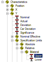
Step 55: Define Feature Characteristic - Diameter Upper Tolerance
Locate the node “D Nom” that was created in the previous step.
Right-click “D Nom”.
Select Duplicate Characteristic from the context menu.
Double-click "D Nom (1)".
In the Characteristic Properties dialog:
Change the label from “D Nom (1)” to “D UT”
Change the color if desired.
Click Associate.
In the Associations dialog:
Select the association Feature>Characteristics>Diameter>Specification Limits>Relative>Bilateral>Upper.
Click Ok.
Click Ok.
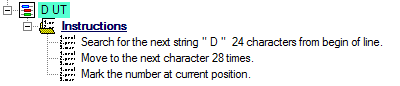
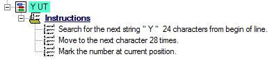
Locate the Instructions node under "D UT".
Define the feature instructions as:
Change the second instruction from "20 times" to "28 times".
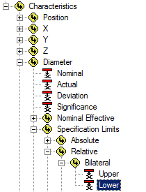
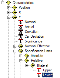
Step 56: Define Feature Characteristic - Diameter Lower Tolerance
Locate the node “D UT” that was created in the previous step.
Right-click “D UT”.
Select Duplicate Characteristic from the context menu.
Double-click "D UT (1)".
In the Characteristic Properties dialog:
Change the label from “D UT (1)” to “D LT”
Change the color if desired.
Click Associate.
In the Associations dialog:
Select the association Feature>Characteristics>Diameter>Specification Limits>Relative>Bilateral>Lower.
Click Ok.
Click Ok.
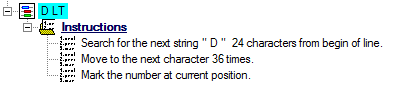
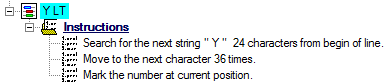
Locate the Instructions node under "D LT".
Define the feature instructions as:
Change the second instruction from "28 times" to "36 times".
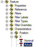
Step 57: Define Feature Characteristic - X Actual
Locate the node “D LT” that was created in the previous step.
Right-click “D LT”.
Select Duplicate Characteristic from the context menu.
Double-click "D LT (1)".
In the Characteristic Properties dialog:
Change the label from “D LT (1)” to “X Act”
Change the color if desired.
Click Associate.
In the Associations dialog:
Select the association Feature>Characteristics>X>Actual.
Click Ok.
Click Ok.
Locate the Instructions node under "X Act".
Define the feature instructions as:
Change the first instruction from " D " to " X "
Change the second instruction from "36 times" to "9 times".
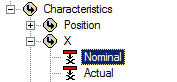
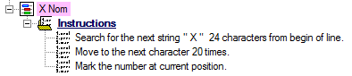
Step 58: Define Feature Characteristic - X Nominal
Locate the node “X Act” that was created in the previous step.
Right-click “X Act”.
Select Duplicate Characteristic from the context menu.
Double-click "X Act (1)".
In the Characteristic Properties dialog:
Change the label from “X Act (1)” to “X Nom”
Change the color if desired.
Click Associate.
In the Associations dialog:
Select the association Feature>Characteristics>X>Nominal.
Click Ok.
Click Ok.
Locate the Instructions node under "X Nom".
Define the feature instructions as:
Change the second instruction from "9 times" to "20 times".
Step 59: Define Feature Characteristic - X Upper Tolerance
Locate the node “X Nom” that was created in the previous step.
Right-click “X Nom”.
Select Duplicate Characteristic from the context menu.
Double-click "X Nom (1)".
In the Characteristic Properties dialog:
Change the label from “X Nom (1)” to “X UT”
Change the color if desired.
Click Associate.
In the Associations dialog:
Select the association Feature>Characteristics>X>Specification Limits>Relative>Bilateral>Upper.
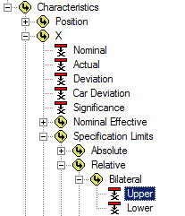
Click Ok.
Click Ok.
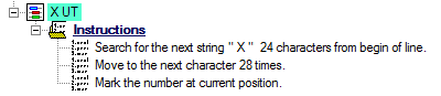
Locate the Instructions node under "X UT".
Define the feature instructions as:
Change the second instruction from "20 times" to "28 times".
Step 60: Define Feature Characteristic - X Lower Tolerance
Locate the node “X UT” that was created in the previous step.
Right-click “X UT”.
Select Duplicate Characteristic from the context menu.
Double-click "X UT (1)".
In the Characteristic Properties dialog:
Change the label from “X UT (1)” to “X LT”
Change the color if desired.
Click Associate.
In the Associations dialog:
Select the association Feature>Characteristics>X>Specification Limits>Relative>Bilateral>Lower.
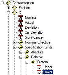
Click Ok.
Click Ok.
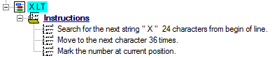
Locate the Instructions node under "X LT".
Define the feature instructions as:
Change the second instruction from "28 times" to "36 times".
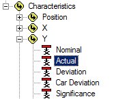
Step 61: Define Feature Characteristic - Y Actual
Locate the node “X LT” that was created in the previous step.
Right-click “X LT”.
Select Duplicate Characteristic from the context menu.
Double-click "X LT (1)".
In the Characteristic Properties dialog:
Change the label from “X LT (1)” to “Y Act”
Change the color if desired.
Click Associate.
In the Associations dialog:
Select the association Feature>Characteristics>Y>Actual.
Click Ok.
Click Ok.
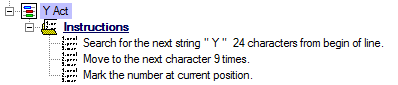
Locate the Instructions node under "Y Act".
Define the feature instructions as:
Change the first instruction from " X " to " Y ".
Change the second instruction from "36 times" to "9 times".
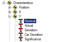
Step 62: Define Feature Characteristic - Y Nominal
Locate the node “Y Act” that was created in the previous step.
Right-click “Y Act”.
Select Duplicate Characteristic from the context menu.
Double-click "Y Act (1)".
In the Characteristic Properties dialog:
Change the label from “Y Act (1)” to “Y Nom”
Change the color if desired.
Click Associate.
In the Associations dialog:
Select the association Feature>Characteristics>Y>Nominal.
Click Ok.
Click Ok.
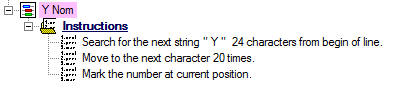
Locate the Instructions node under "Y Nom".
Define the feature instructions as:
Change the second instruction from "9 times" to "20 times".
Step 63: Define Feature Characteristic - Y Upper Tolerance
Locate the node “Y Nom” that was created in the previous step.
Right-click “Y Nom”.
Select Duplicate Characteristic from the context menu.
Double-click "Y Nom (1)".
In the Characteristic Properties dialog:
Change the label from “Y Nom (1)” to “Y UT”
Change the color if desired.
Click Associate.
In the Associations dialog:
Select the association Feature>Characteristics>Y>Specification Limits>Relative>Bilateral>Upper.
Click Ok.
Click Ok.
Locate the Instructions node under "Y UT".
Define the feature instructions as:
Change the second instruction from "20 times" to "28 times".
Step 64: Define Feature Characteristic - Y Lower Tolerance
Locate the node “Y UT” that was created in the previous step.
Right-click “Y UT”.
Select Duplicate Characteristic from the context menu.
Double-click "Y UT (1)".
In the Characteristic Properties dialog:
Change the label from “Y UT (1)” to “Y LT”
Change the color if desired.
Click Associate.
In the Associations dialog:
Select the association Feature>Characteristics>Y>Specification Limits>Relative>Bilateral>Lower.
Click Ok.
Click Ok.
Locate the Instructions node under "Y LT".
Define the feature instructions as:
Change the second instruction from "28 times" to "36 times".
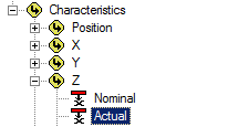
Step 65: Define Feature Characteristic - Z Actual
Locate the node “Y LT” that was created in the previous step.
Right-click “Y LT”.
Select Duplicate Characteristic from the context menu.
Double-click "Y LT (1)".
In the Characteristic Properties dialog:
Change the label from “Y LT (1)” to “Z Act”
Change the color if desired.
Click Associate.
In the Associations dialog:
Select the association Feature>Characteristics>Z>Actual.
Click Ok.
Click Ok.
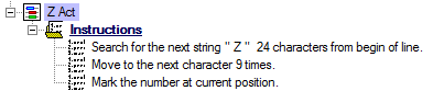
Locate the Instructions node under "Z Act".
Define the feature instructions as:
Change the first instruction from " Y " to " Z ".
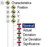
Step 66: Define Feature Characteristic - Z Nominal
Locate the node “Z Act” that was created in the previous step.
Right-click “Z Act”.
Select Duplicate Characteristic from the context menu.
Double-click "Z Act (1)".
In the Characteristic Properties dialog:
Change the label from “Z Act (1)” to “Z Nom”
Change the color if desired.
Click Associate.
In the Associations dialog:
Select the association Feature>Characteristics>Z>Nominal.
Click Ok.
Click Ok.
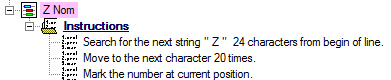
Locate the Instructions node under "Z Nom".
Define the feature instructions as:
Change the second instruction from "9 times" to "20 times".
Step 67: Define Feature Characteristic - Z Upper Tolerance
Locate the node “Z Nom” that was created in the previous step.
Right-click “Z Nom”.
Select Duplicate Characteristic from the context menu.
Double-click "Z Nom (1)".
In the Characteristic Properties dialog:
Change the label from “Z Nom (1)” to “Z UT”
Change the color if desired.
Click Associate.
In the Associations dialog:
Select the association Feature>Characteristics>Z>Specification Limits>Relative>Bilateral>Upper.
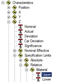
Click Ok.
Click Ok.
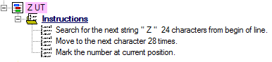
Locate the Instructions node under "Z UT".
Define the feature instructions as:
Change the second instruction from "20 times" to "28 times".
Step 68: Define Feature Characteristic - Z Lower Tolerance
Locate the node “Z UT” that was created in the previous step.
Right-click “Z UT”.
Select Duplicate Characteristic from the context menu.
Double-click "Z UT (1)".
In the Characteristic Properties dialog:
Change the label from “Z UT (1)” to “Z LT”
Change the color if desired.
Click Associate.
In the Associations dialog:
Select the association Feature>Characteristics>Z>Specification Limits>Relative>Bilateral>Lower.
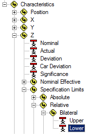
Click Ok.
Click Ok.
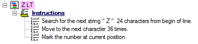
Locate the Instructions node under "Z LT".
Define the feature instructions as:
Change the second instruction from "28 times" to "36 times".
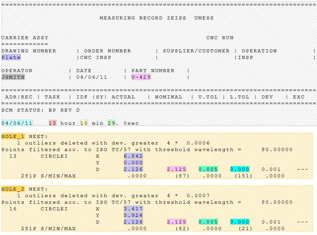
Step 69: Review Results for Plate Actuals
Below are screen captures of what the file highlighting and the grid in DataSmith will look like once all of the steps have been completed for the Plate Actuals configuration. Compare the screen captures to your finished results to confirm that all of the steps were completed successfully.
The file should now look like this:
Show/Hide ScreenshotShow/Hide Screenshot
Switch the main window from the Plate U-425.rtxt tab to the Grid tab.
The grid should look like this:
 Show/Hide ScreenshotShow/Hide Screenshot

You have reached the end of the Plate Tutorial, and are now ready to read the Plate data into your Database!