Introduction
The "Yoke" tutorial demonstrates how build three separate Configs for nominal, actual, and constructed feature data into a single DataSmith translator. The demo data for this tutorial is in CSV format.
DataSmith concepts demonstrated:
-
Constructed Features
-
Tie Features
-
Multiple Configurations
-
Mangle
To complete this tutorial:
Download the data files here. Save the zip file and extract the files.
Run DataSmith.
Create a new translator file.
Follow steps below.
When you are finished, compare your result with the screen shots shown in the Review section at the end of this topic.
Nominals Config
Step 1: Getting Started
Right-click the top node of the Configurations tree (labeled with the DataSmith document name).
Select New Config from the context menu.
Step 2: Modify the Config
Locate the new config on the Configurations tree.
New configs are usually added to tree after any other existing configs.
The new config is likely called “Config A”.
Double-click "Config A".
In the Modify Config dialog:
Change the config label to “Yoke Nominals”.
Enter the text ”nom” into the Extensions field.
Click Ok.
From this step onward, all nodes referred to will be located within the "Yoke Nominals" config.
Step 3: Load a File
Make sure the config you just created is selected in the tree.
Select Add Files from the File menu or click the Add Files toolbar button.
Browse to the folder containing the Yoke translator.
Select and open the file Yoke.nom.
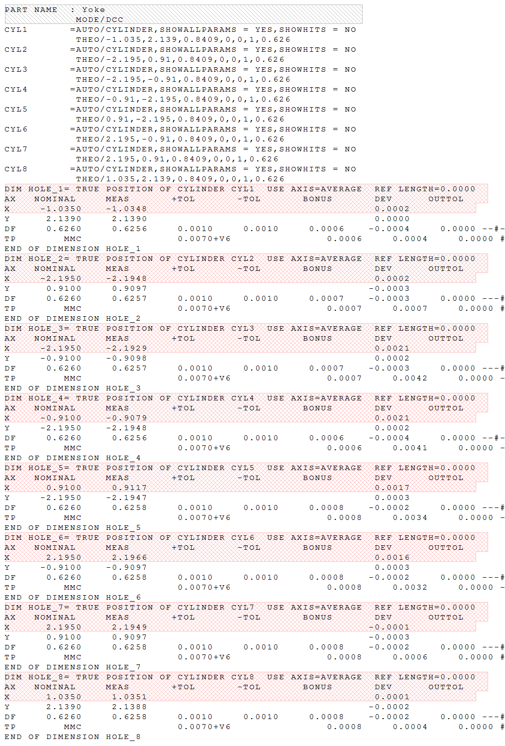
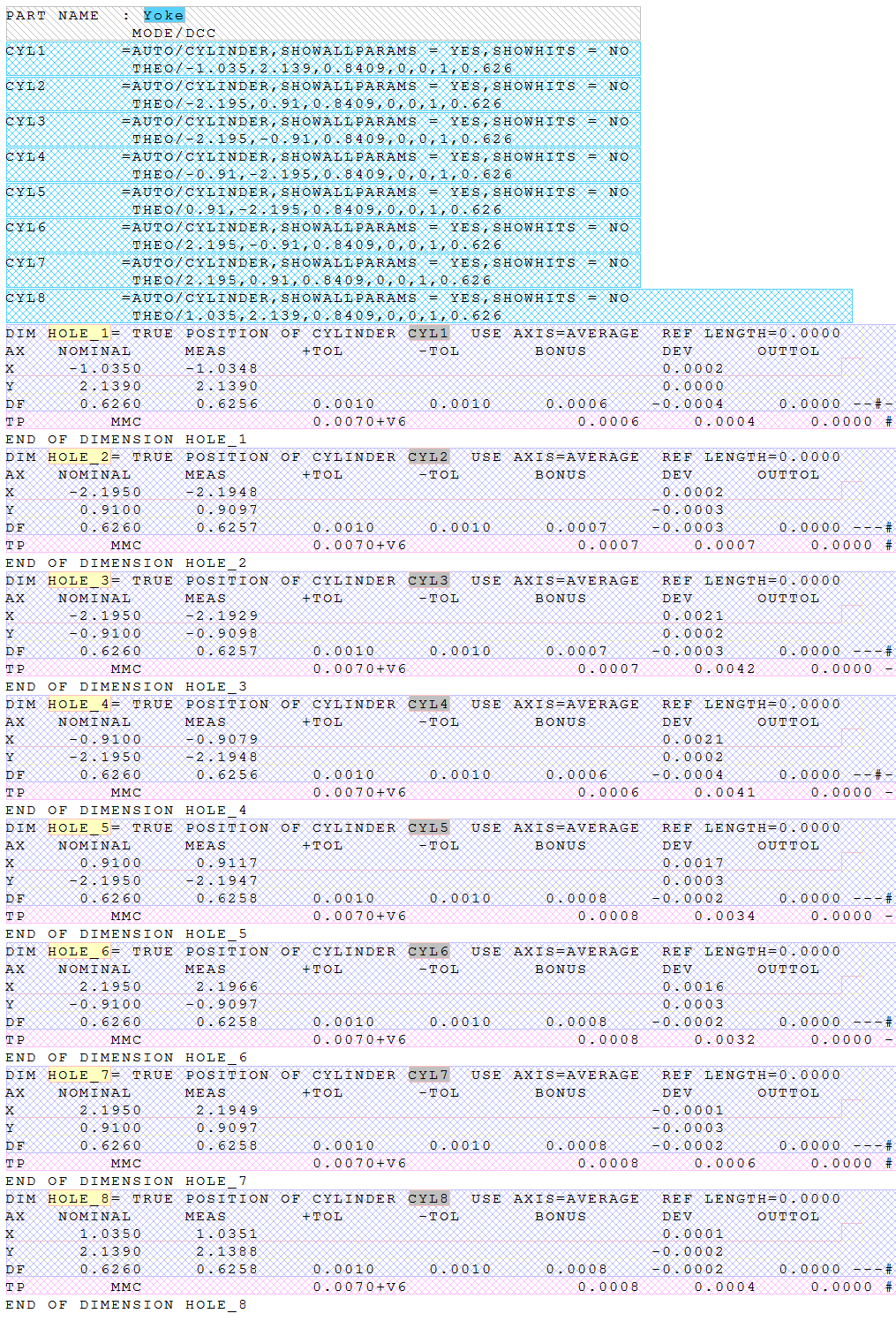
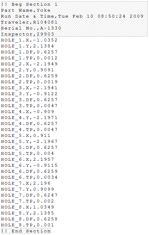
The raw file "Yoke.nom" will be displayed in the main window area.
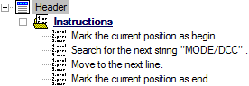
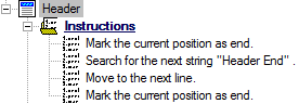
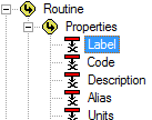
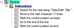
Step 4: Define the Header
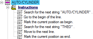
Locate the Instructions node under the Header node.
Define the instructions as:
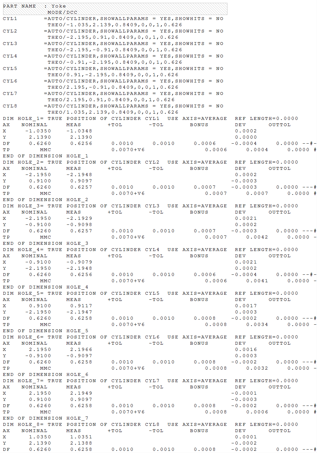
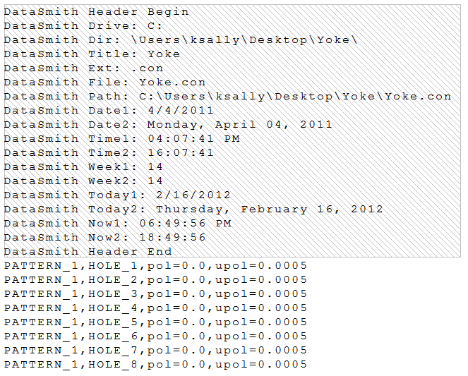
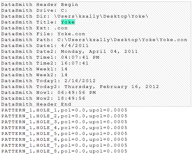
The file should now look like this:
 Show/Hide ScreenshotShow/Hide Screenshot
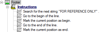
Step 5: Define the Footer
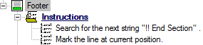
Locate the Instructions node under the Footer node.
Define the instructions as:
Step 6: Define a Feature
Locate the node labeled “Feature A” under the Features node.
Double-click "Feature A".
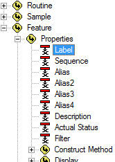
In the Feature Properties dialog:
Change the feature label to “X”.
Change the color if desired.
Select the check box "Is MasterTie".
Click Ok.
Locate the Instructions node under "X".
Define the instructions as:
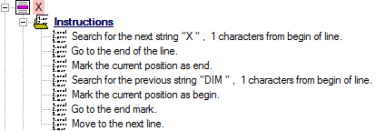
The file should now look like this:
Show/Hide ScreenshotShow/Hide Screenshot
Step 7: Define More Features
Locate the Feature labeled "X" that you created in the previous step.
Duplicate Feature "X".
Double-click "Copy A of X".
In the Feature Properties dialog:
Change the feature label to “Y”.
Change the color if desired.
Click Ok.
Locate the Instructions node under "Y".
Change the string in the first instruction to "Y".
Duplicate Feature "Y".
Double-click "Copy A of Y".
In the Feature Properties dialog:
Change the feature label to “TP”.
Change the color if desired.
Click Ok.
Locate the Instructions node under "TP".
Change the string in the first instruction to "TP".
Duplicate Feature "TP".
Double-click "Copy A of TP".
In the Feature Properties dialog:
Change the feature label to “DF”.
Change the color if desired.
Click Ok.
Locate the Instructions node un der "DF".
Change the string in the first instruction to "DF".
Duplicate Feature "DF".
Double-click "Copy A of DF".
In the Feature Properties dialog:
Change the feature label to “AUTO/CYLINDER”.
Change the color if desired.
Uncheck the check box "Is MasterTie".
Click Ok.
Locate the Instructions node under "AUTO/CYLINDER".
Define the instructions as:
The file should now look like this:
Show/Hide ScreenshotShow/Hide Screenshot
Step 8: Define Header Characteristics
Locate the Characteristics node under the Header node.
Right-click on the Characteristics node
Select New Characteristic from the context menu.
Locate the node labeled “Characteristic A” under the Characteristics node.
Double-click "Characteristic A".
In the Characteristic Properties dialog:
Change the label to “Routine”.
Change the color if desired.
Click Associate.
In the Associations dialog:
Select the association Routine>Properties>Label.
 Show/Hide ScreenshotShow/Hide Screenshot
Click Ok.
Click Ok.
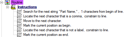
Locate the Instructions node under "Routine".
Define the instructions as:
Create a New Characteristic.
Locate the node labeled “Characteristic A” under the Characteristics node.
Double-click "Characteristic A".
In the Characteristic Properties dialog:
Change the label to “Image path”.
Change the color if desired.
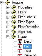
Click Associate.
In the Associations dialog:
Select the association Routine>Image>Path.
Show/Hide ScreenshotShow/Hide Screenshot
Click Ok.
In the Default String field, enter the path: "Variable "ReporterLibImages" is not defined".
Click Ok.
Delete all Undefined instructions for the "Image path" characteristic, if desired.
Create a New Characteristic.
Locate the node labeled “Characteristic A” under the Characteristics node.
Double-click "Characteristic A".
In the Characteristic Properties dialog:
Change the label to “Image”.
Change the color if desired.
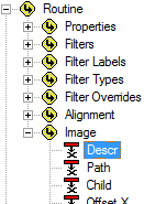
Click Associate.
In the Associations dialog:
Select the association Routine>Image>Descr.
Show/Hide ScreenshotShow/Hide Screenshot
Click Ok.
In the Default String field, enter "Yoke".
Click Ok.
Delete all Undefined instructions for the "Image" characteristic, if desired.
Create a New Characteristic.
Locate the node labeled “Characteristic A” under the Characteristics node.
Double-click "Characteristic A".
In the Characteristic Properties dialog:
Change the label to “Units”.
Change the color if desired.
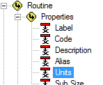
Click Associate.
In the Associations dialog:
Select the association Routine>Properties>Units.
Show/Hide ScreenshotShow/Hide Screenshot
Click Ok.
In the Default String field, enter "2".
Click Ok.
Delete all Undefined instructions for the "Image" characteristic, if desired.
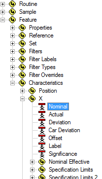
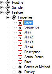
Step 9: Define Feature Characteristics - Feature X
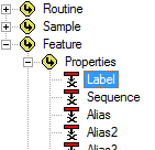
Locate the Characteristics node under the “X” node.
Right-click on the Characteristics node.
Select New Characteristic from the context menu.
Locate the node labeled “Characteristic A” under the Characteristics node.
Double-click “Characteristic A”.
In the Characteristic Properties dialog:
Change the characteristic label to “Label”.
Change the color if desired.
Click Associate.
In the Associations dialog:
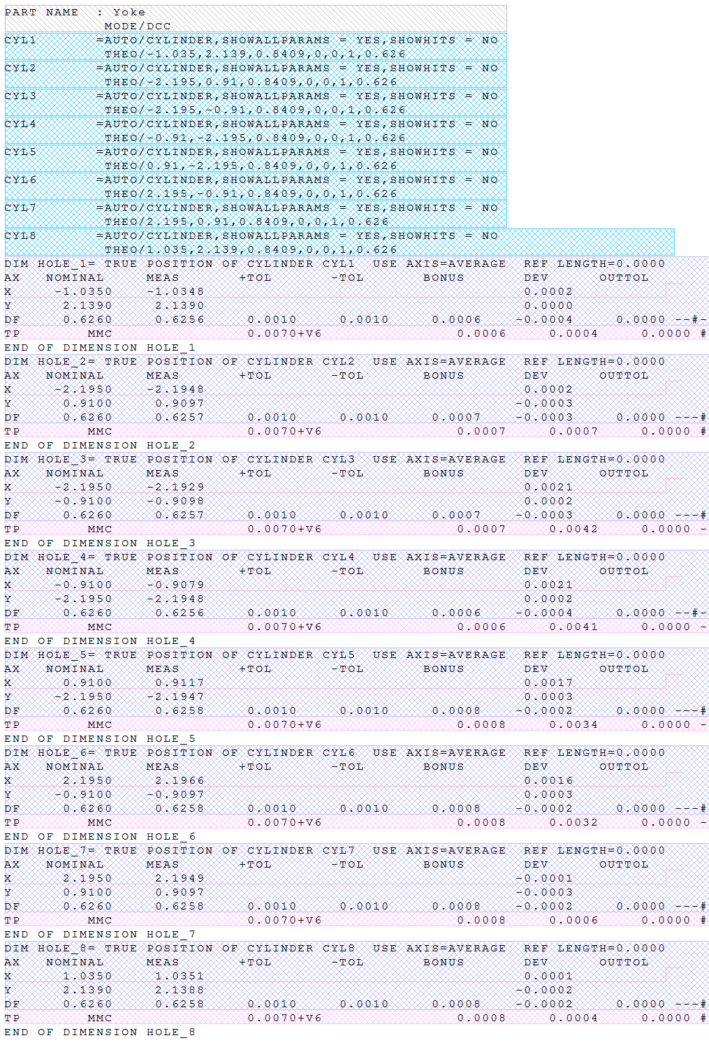
Select the association Feature>Properties>Label.
Show/Hide ScreenshotShow/Hide Screenshot
Click Ok.
Click Ok.
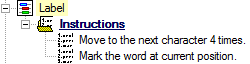
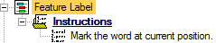
Locate the Instructions node under "Label".
Define the instructions as:
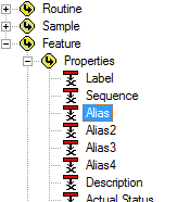
Create a New Characteristic.
Locate the node labeled “Characteristic A” under the Characteristics node.
Double-click “Characteristic A”.
In the Characteristic Properties dialog:
Change the characteristic label to “3D Label”.
Change the color if desired.
Click Associate.
In the Associations dialog:
Select the association Feature>Properties>Alias.
Show/Hide ScreenshotShow/Hide Screenshot
Click Ok.
Select the check box "Tie".
Click Ok.
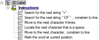
Locate the Instructions node under "3D Label".
Define the instructions as:
The file should now look like this:
Show/Hide ScreenshotShow/Hide Screenshot
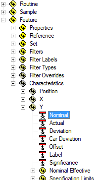
Step 10: Define Feature Characteristics – Feature Y
Right-click on the Characteristics under the “X” node.
Select Copy Characteristics from the context menu.
Right-click on the Characteristics node under the "Y" node.
Select Paste Characteristics from the context menu.
Step 11: Define Feature Characteristics – Feature TP
Repeat the previous step, except Paste Characteristics into the Characteristics node under the "TP" node.
Select New Characteristic from the context menu.
In the Characteristic Properties dialog:
Change the characteristic label to “Nom”.
Change the color if desired.
Click Associate.
In the Associations dialog:
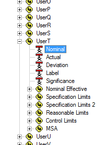
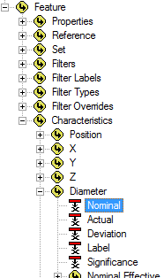
Select the association Feature>Characteristics>UserT>Nominal.
Show/Hide ScreenshotShow/Hide Screenshot
Click Ok.
Set the Type Validation to "Real (decimal value)".
Click Ok.
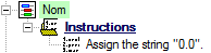
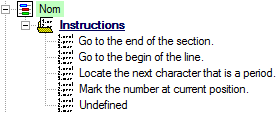
Locate the Instructions node under "Nom".
Define the instructions as:
Create a New Characteristic.
In the Characteristic Properties dialog:
Change the characteristic label to “Upper Pol”.
Change the color if desired.
Click Associate.
In the Associations dialog:
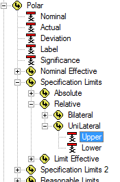
Select the association Feature>Characteristics>Polar>Specification Limits>Relative>UniLateral>Upper.
Show/Hide ScreenshotShow/Hide Screenshot
Click Ok.
Set the Type Validation to "Real (decimal value)".
In the Default String field, enter ".001".
Click Ok.
Delete all Undefined instructions for the "Upper Pol" characteristic, if desired.
Step 12: Define Feature Characteristics – Feature DF
Copy the Characteristics from the "TP" node and paste them into the Characteristics node under the "DF" node.
Locate the node labeled “Nom" under the Characteristics node.
In the Characteristic Properties dialog:
Click Associate.
In the Associations dialog:
Change the association to Feature>Characteristics>Diameter>Nominal.
Show/Hide ScreenshotShow/Hide Screenshot
Click Ok.
Click Ok.
Locate the Instructions node under "Nom".
Define the instructions as:
Locate the node labeled “Upper Pol" under the Characteristics node.
In the Characteristic Properties dialog:
Change the characteristic label to “Upper bi”.
Change the color if desired.
Click Associate.
In the Associations dialog:
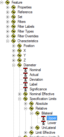
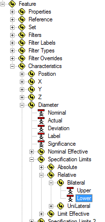
Change the association to Feature>Characteristics>Diameter>Specification Limits>Relative>Bilateral>Upper.
Show/Hide ScreenshotShow/Hide Screenshot
Click Ok.
Clear the text from the Default String field.
Click Ok.
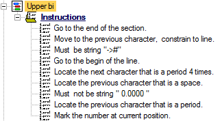
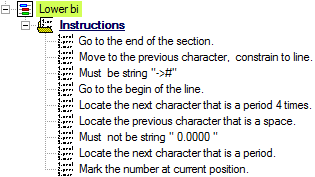
Locate the Instructions node under "Upper bi".
Define the instructions as:
Duplicate the characteristic "Upper bi" that you just created.
Locate the node labeled “Upper Pol (1)”.
In the Characteristic Properties dialog:
Change the characteristic label to “Lower bi”.
Change the color if desired.
Click Associate.
In the Associations dialog:
Change the association from Upper to Lower.
Show/Hide ScreenshotShow/Hide Screenshot
Click Ok.
Click Ok.
Locate the Instructions node under "Lower bi".
Change the eighth instruction from "previous" to "next".
The file should now look like this:
Show/Hide ScreenshotShow/Hide Screenshot
Step 13: Define Feature Characteristics – Feature AUTO/CYLINDER
Locate the Characteristics node under the “AUTO/CYLINDER” node.
Create a New Characteristic.
Open the Characteristic Properties dialog:
Change the characteristic label to “Label”.
Change the color if desired.
Select the check box "Tie".
Click Ok.
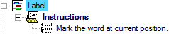
Locate the Instructions node under "Label".
Define the instructions as:
Create a New Characteristic.
In the Characteristic Properties dialog:
Change the characteristic label to “X 3D”.
Change the color if desired.
Click Associate.
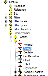
In the Associations dialog:
Select the association Feature>Characteristics>X>Nominal.
Show/Hide ScreenshotShow/Hide Screenshot
Click Ok.
Set the Type Validation to "Real (decimal value)".
Click Ok.
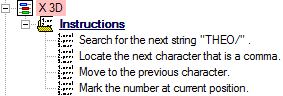
Locate the Instructions node under "X 3D".
Define the instructions as:
Duplicate the characteristic "X 3D" that you just created.
In the Characteristic Properties dialog:
Change the characteristic label from "X 3D (1)" to “Y 3D”.
Change the color if desired.
Click Associate.
In the Associations dialog:
Change the association to Feature>Characteristics>Y>Nominal.
Show/Hide ScreenshotShow/Hide Screenshot
Click Ok.
Click Ok.
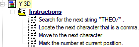
Locate the Instructions node under "Y 3D".
Change the third instruction from "previous" to "next"as:
Duplicate the characteristic "Y 3D".
In the Characteristic Properties dialog:
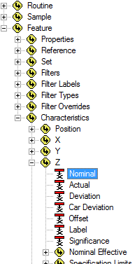
Change the characteristic label from "Y 3D (1)" to “Z 3D”.
Change the color if desired.
Click Associate.
In the Associations dialog:
Change the association to Feature>Characteristics>Z>Nominal.
Show/Hide ScreenshotShow/Hide Screenshot
Click Ok.
Click Ok.
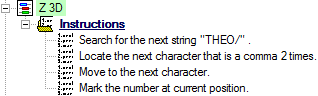
Locate the Instructions node under "Z 3D".
Change the second instruction from "comma" to "comma 2 times".
Duplicate the characteristic "Z 3D".
In the Characteristic Properties dialog:
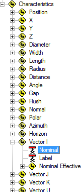
Change the characteristic label from "Z 3D (1)" to “I”.
Change the color if desired.
Click Associate.
In the Associations dialog:
Change the association to Feature>Characteristics>Vector I>Nominal.
Show/Hide ScreenshotShow/Hide Screenshot
Click Ok.
Click Ok.
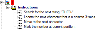
Locate the Instructions node under "I".
Change the second instruction from "comma 2 times" to "comma 3 times".
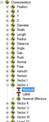
Duplicate the characteristic "I".
In the Characteristic Properties dialog:
Change the characteristic label from "I" to “J”.
Change the color if desired.
Click Associate.
In the Associations dialog:
Change the association to Feature>Characteristics>Vector J>Nominal.
Show/Hide ScreenshotShow/Hide Screenshot
Click Ok.
Click Ok.
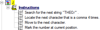
Locate the Instructions node under "J".
Change the second instruction from "comma 3 times" to "comma 4 times".
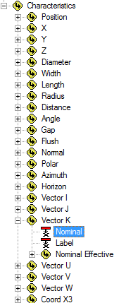
Duplicate the characteristic "J".
In the Characteristic Properties dialog:
Change the characteristic label from "J" to “K”.
Change the color if desired.
Click Associate.
In the Associations dialog:
Change the association to Feature>Characteristics>Vector K>Nominal.
Show/Hide ScreenshotShow/Hide Screenshot
Click Ok.
Click Ok.
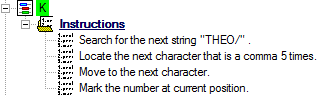
Locate the Instructions node under "K".
Change the second instruction from "comma 4 times" to "comma 5 times".
Create a New Characteristic.
In the Characteristic Properties dialog:
Change the characteristic label to “Nor”.
Change the color if desired.
Click Associate.
In the Associations dialog:
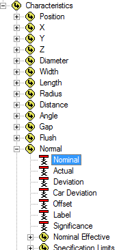
Select the association Feature>Characteristics>Normal>Nominal.
Show/Hide ScreenshotShow/Hide Screenshot
Click Ok.
In the Default String field, enter "0.0".
Click Ok.
Delete all Undefined instructions for the "Nor" characteristic, if desired.
Duplicate the characteristic "Nor" that you just created.
In the Characteristic Properties dialog:
Change the characteristic label from "Nor (1)" to “Pol”.
Change the color if desired.
Click Associate.
In the Associations dialog:
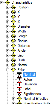
Change the association to Feature>Characteristics>Polar>Nominal.
Show/Hide ScreenshotShow/Hide Screenshot
Click Ok.
Click Ok.
Step 14: Review Results for Yoke Nominals
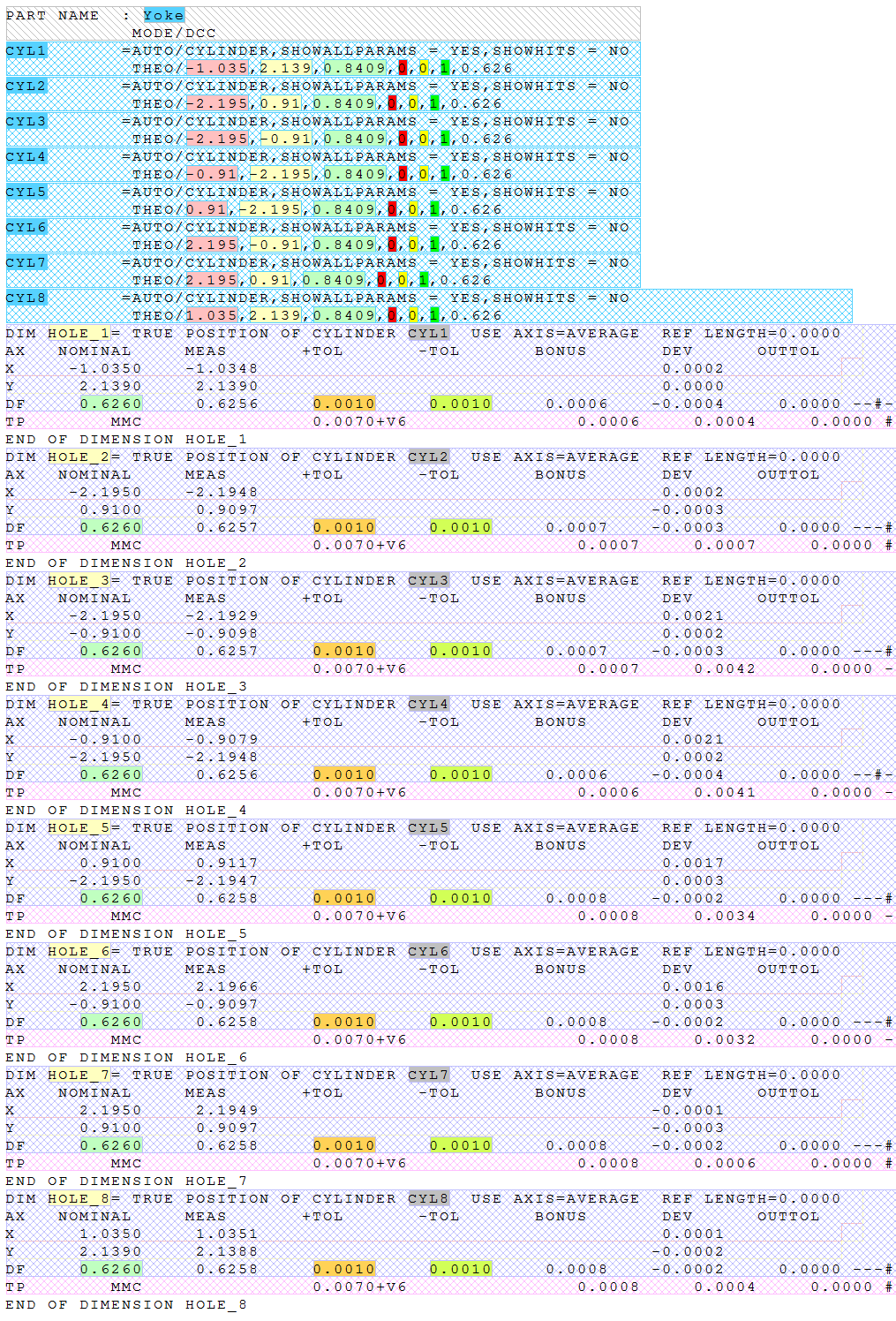
Below are screen captures of what the file highlighting and the grid in DataSmith will look like once all of the steps have been completed for the Yoke Nominals configuration. Compare the screen captures to your finished results to confirm that all of the steps were completed successfully.
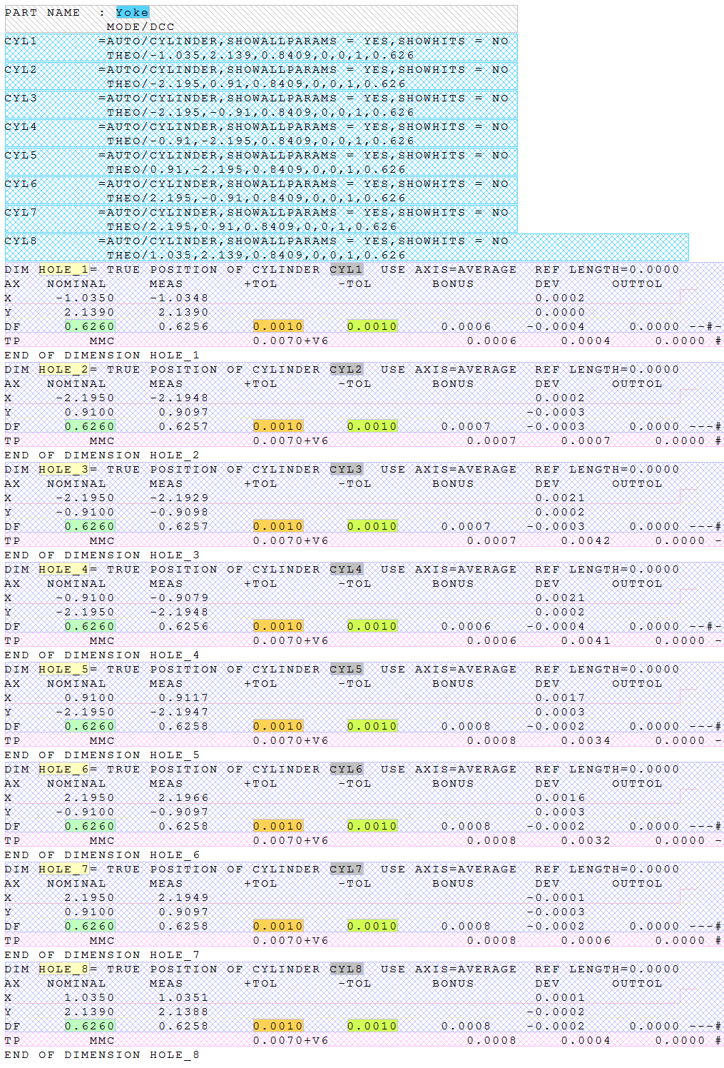
The file should now look like this:
Show/Hide ScreenshotShow/Hide Screenshot
Switch the main window from the Yoke.nom tab to the Grid tab.
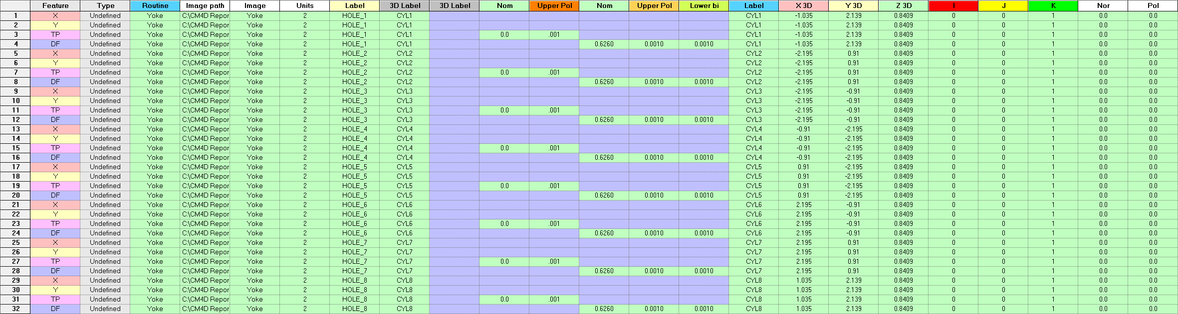
The grid should look like this:
 Show/Hide ScreenshotShow/Hide Screenshot
Once you have completed the first 13 steps, save your DataSmith document and continue on to Step 15.
Constructed Features Config
Step 15: Create and Modify a Second Config
Right-click the top node of the Configurations tree (labeled with the DataSmith document name).
Select New Config from the context menu.
Locate the new config on the Configurations tree.
Open the Modify Config dialog:
Change the Config label to "Yoke Constructions".
Enter the text ”con” into the Extensions field.
Select the check box "Insert Header"
From this step onward, all nodes referred to will be located within the Yoke Constructions config.
Step 16: Load a File
Make sure the config you just created is selected in the tree.
Select Add Files from the File menu or click the Add Files toolbar button.
Browse to the folder containing the Yoke translator.
Select and open the file “Yoke.con”.
The raw file "Yoke.con" will be displayed in the main window area.
Step 17: Define the Header
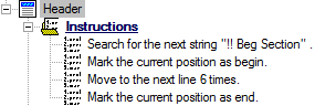
Locate the Instructions node under the Header node.
Define the instructions as:
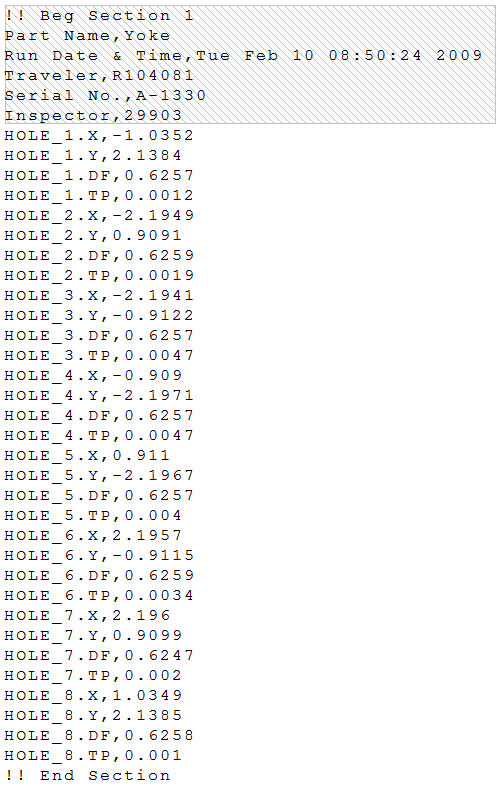
To view a screenshot of the expected results, click the link below:
Show/Hide ScreenshotShow/Hide Screenshot
Step 18: Define a Feature
Locate the node labeled “Feature A” under the Features node.
Open the Feature Properties dialog:
Change the feature label to “Polar”.
Change the color if desired.
Click Ok.
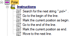
Locate the Instructions node under "Polar".
Define the instructions as:
To view a screenshot of the expected results, click the link below:
Show/Hide ScreenshotShow/Hide Screenshot
Step 19: Define Header Characteristics
Locate the Characteristics node under the Header node.
Create a New Characteristic.
Open the Characteristic Properties for "Characteristic A".
Change the label to “Routine”.
Change the color if desired.
Click Associate.
In the Associations dialog:
Select the association Routine>Properties>Label.
Show/Hide ScreenshotShow/Hide Screenshot
Click Ok.
Click Ok.
Locate the Instructions node under "Routine".
Define the instructions as:
To view a screenshot of the expected results, click the link below:
Show/Hide ScreenshotShow/Hide Screenshot
Step 20: Define Feature Characteristics
Locate the Characteristics node under the “Polar” node.
Create a New Characteristic.
Open the Characteristic Properties for "Characteristic A".
Change the characteristic label to “Label”.
Change the color if desired.
Click Associate.
In the Associations dialog:
Select the association Feature>Properties>Label.
Show/Hide ScreenshotShow/Hide Screenshot
Click Ok.
Click Ok.
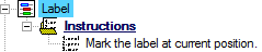
Locate the Instructions node under "Label".
Define the instructions as:
Create a New Characteristic.
Open the Characteristic Properties.
Change the characteristic label to “Ref”.
Change the color if desired.
Click Associate.
In the Associations dialog:
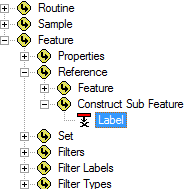
Select the association Feature>Reference>Construct Sub Feature>Label.
Show/Hide ScreenshotShow/Hide Screenshot
Click Ok.
Click Ok.
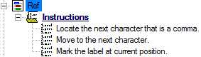
Locate the Instructions node under "Ref".
Define the instructions as:
Create a New Characteristic.
Open the Characteristic Properties.
Change the characteristic label to “Cons”.
Change the color if desired.
Click Associate.
In the Associations dialog:
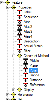
Select the association Feature>Properties>Construct Method>Polar.
Show/Hide ScreenshotShow/Hide Screenshot
Click Ok.
In the Default String field, enter "Range".
Click Ok.
Delete all Undefined instructions for the "Cons" characteristic, if desired.
Create a New Characteristic.
Open the Characteristic Properties.
Change the characteristic label to “Nom Polar”.
Change the color if desired.
Click Associate.
In the Associations dialog:
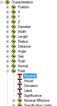
Select the association Feature>Characteristics>Polar>Nominal.
Show/Hide ScreenshotShow/Hide Screenshot
Click Ok.
Set the Type Validation to "Real (decimal value)".
Click Ok.
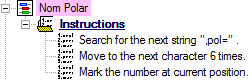
Locate the Instructions node under "Nom Polar".
Define the instructions as:
Duplicate the characteristic "Nom Polar".
Open the Characteristic Properties.
Change the characteristic label to “Upper Polar”.
Change the color if desired.
Click Associate.
In the Associations dialog:
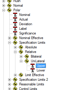
Change the association to Feature>Characteristics>Polar>Specification Limits>Relative>UniLateral>Upper.
Show/Hide ScreenshotShow/Hide Screenshot
Click Ok.
Click Ok.
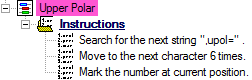
Locate the Instructions node under "Upper Polar".
Change the first instruction string from ",pol=" to ",upol="
Step 21: Review Results for Yoke Constructions
Below are screen captures of what the file highlighting and the grid in DataSmith will look like once all of the steps have been completed for the Yoke Constructions configuration. Compare the screen captures to your finished results to confirm that all of the steps were completed successfully.
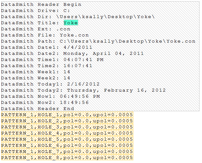
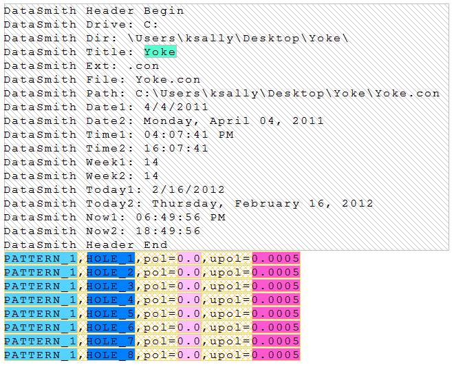
The file should now look like this:
Show/Hide ScreenshotShow/Hide Screenshot
Switch the main window from the Yoke.con tab to the Grid tab.
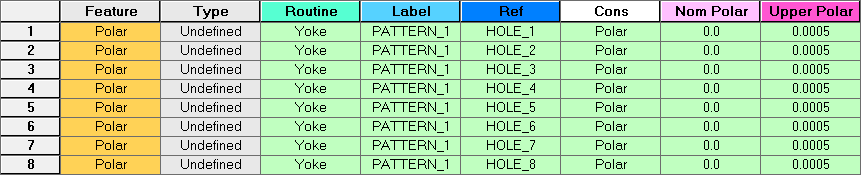
The grid should look like this:
Show/Hide ScreenshotShow/Hide Screenshot
Once you have completed the first 21 steps, save your DataSmith document and continue on to Step 22.
Actuals Config
Step 22: Create and Modify a Third Config
Right-click the top node of the Configurations tree (labeled with the DataSmith document name).
Select New Config from the context menu.
Locate the new config on the Configurations tree.
Open the Modify Config dialog:
Change the Config label to "Yoke Actuals".
Select the check box "CSV"
From this step onward, all nodes referred to will be located within the Yoke Actuals config.
Step 23: Load a File
Make sure the config you just created is selected in the tree.
Select Add Files from the File menu or click the Add Files toolbar button.
Browse to the folder containing the Yoke translator.
Select and open the file Yoke-1330.csv.
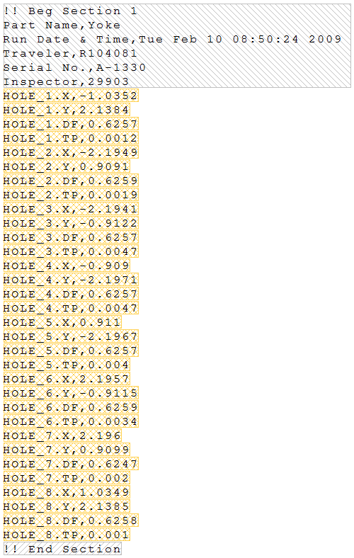
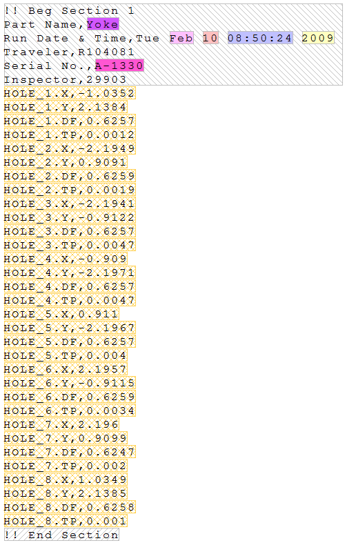
The raw file Yoke-1330.csv will be displayed in the main window area.
Step 24: Define the Header
Locate the Instructions node under the Header node.
Define the instructions as:
To view a screenshot of the expected results, click the link below:
Show/Hide ScreenshotShow/Hide Screenshot
Step 25: Define the Footer
Locate the Instructions node under the Footer node.
Define the instructions as:
To view a screenshot of the expected results, click the link below:
Show/Hide ScreenshotShow/Hide Screenshot
Step 26: Define a Feature
Locate the node labeled “Feature A” under the Features node.
Open the Feature Properties dialog:
Change the feature label to “Line”.
Change the color if desired.
Click Ok.
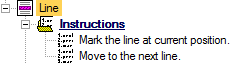
Locate the Instructions node under "Line".
Define the instructions as:
To view a screenshot of the expected results, click the link below:
Show/Hide ScreenshotShow/Hide Screenshot
Step 27: Define Header Characteristics
Locate the Characteristics node under the Header node.
Create a New Characteristic.
Open the Characteristic Properties for "Characteristic A".
Change the label to “Routine”.
Change the color if desired.
Click Associate.
In the Associations dialog:
Select the association Routine>Properties>Label.
Show/Hide ScreenshotShow/Hide Screenshot
Click Ok.
Click Ok.
Locate the Instructions node under "Routine".
Define the instructions as:
Duplicate the characteristic "Routine".
Open the Characteristic Properties for "Routine (1)".
Change the label to “Sample”.
Change the color if desired.
Click Associate.
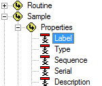
In the Associations dialog:
Select the association Sample>Properties>Label.
Show/Hide ScreenshotShow/Hide Screenshot
Click Ok.
Click Ok.
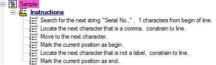
Locate the Instructions node under "Sample".
Change the first instruction string from "Part Name" to "Serial No.,"
Create a New Characteristic.
Open the Characteristic Properties for "Characteristic A".
Change the label to “Year”.
Change the color if desired.
Click Associate.
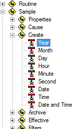
In the Associations dialog:
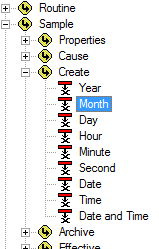
Select the association Sample>Create>Year.
Show/Hide ScreenshotShow/Hide Screenshot
Click Ok.
Uncheck the check box "Visible to Output".
Set the Type Validation to "Integer (whole number)".
Click Ok.
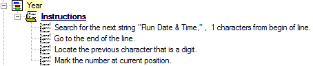
Locate the Instructions node under "Year".
Define the instructions as:
Duplicate the characteristic "Year".
Open the Characteristic Properties for "Year (1)".
Change the label to “Month”.
Change the color if desired.
Click Associate.
In the Associations dialog:
Change the association to Sample>Create>Month.
Show/Hide ScreenshotShow/Hide Screenshot
Click Ok.
Set the Type Validation to "Text".
Click Ok.
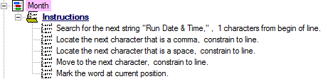
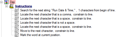
Locate the Instructions node under "Month".
Change the first instruction from "any character position"" to "1 characters from begin of line".
Change the second instruction to "Locate the next character that is a comma, constrain to line".
Change the third instruction to "next character", "space", and "constrain to line".
Right-click the fourth instruction and select Insert New Instruction.
Set the new instruction to "Move to the next character, constrain to line".
Change the last instruction from "number" to "word".
Duplicate the characteristic "Month".
Open the Characteristic Properties for "Month (1)".
Change the label to “Day”.
Change the color if desired.
Click Associate.
In the Associations dialog:
Change the association to Sample>Create>Day.
Show/Hide ScreenshotShow/Hide Screenshot
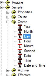
Click Ok.
Set the Type Validation to "Integer (whole number)".
Click Ok.
Locate the Instructions node under "Day".
Right click the third instruction and select Copy Instruction.
Right-click the third instruction and select Paste Instruction twice.
Change the new fourth instruction to "not a space" and "do not constrain".
Duplicate the characteristic "Day".
Open the Characteristic Properties for "Day (1)".
Change the label to “Time”.
Change the color if desired.
Click Associate.
In the Associations dialog:
Change the association to Sample>Create>Time.
Show/Hide ScreenshotShow/Hide Screenshot
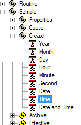
Click Ok.
Set the Type Validation to "Time (time only)".
Click Ok.
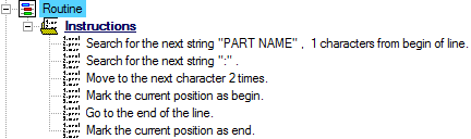
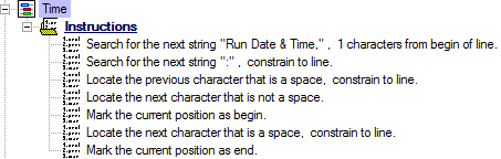
Locate the Instructions node under "Time".
Change the second instruction to "Search for the next string ":", constrain to line.
Change the third instruction to "previous character".
Select the second to last instruction, and drag it up one level to make it the fifth instruction.
Change the new fifth instruction to "Mark the current position as begin".
Change the last instruction to "current position as end".
Create a New Characteristic.
Open the Characteristic Properties for "Characteristic A".
Change the label to “Date Time”.
Change the color if desired.
Click Associate.
In the Associations dialog:
Select the association Sample>Create>Year.
Show/Hide ScreenshotShow/Hide Screenshot
Click Ok.
Click Mangle.
Select the "Format" radio button and enter the following string in the field: "~Month~/~Day~/~Year~ ~Time~"
Click OK.
Set the Type Validation to "DateTime (date and time)".
Click Ok.
Delete all Undefined instructions for the "Date Time" characteristic, if desired.
To view a screenshot of the expected results, click the link below:
Show/Hide ScreenshotShow/Hide Screenshot
Step 28: Define Feature Characteristics
Locate the Characteristics node under the “Range” node.
Create a New Characteristic.
Open the Characteristic Properties for "Characteristic A".
Change the characteristic label to “Feature Label”.
Change the color if desired.
Click Associate.
In the Associations dialog:
Select the association Feature>Properties>Label.
Show/Hide ScreenshotShow/Hide Screenshot
Click Ok.
Click Ok.
Locate the Instructions node under "Feature Label".
Define the instructions as:
Create a New Characteristic.
Open the Characteristic Properties.
Change the characteristic label to “X”.
Change the color if desired.
Click Associate.
In the Associations dialog:
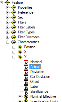
Select the association Feature>Characteristics>X>Actual.
Show/Hide ScreenshotShow/Hide Screenshot
Click Ok.
Set the Type Validation to "Real (decimal value)".
Click Ok.
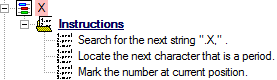
Locate the Instructions node under "X".
Define the instructions as:
Duplicate the characteristic "X".
Open the Characteristic Properties.
Change the characteristic label to “Y”.
Change the color if desired.
Click Associate.
In the Associations dialog:
Change the association to Feature>Characteristics>Y>Actual.
Show/Hide ScreenshotShow/Hide Screenshot
Click Ok.
Click Ok.
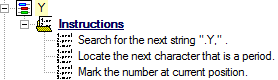
Locate the Instructions node under "Y".
Change the first instruction string to ".Y,".
Duplicate the characteristic "Y".
Open the Characteristic Properties.
Change the characteristic label to “DF”.
Change the color if desired.
Click Associate.
In the Associations dialog:
Change the association to Feature>Characteristics>Diameter>Actual.
Show/Hide ScreenshotShow/Hide Screenshot
Click Ok.
Click Ok.
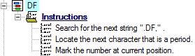
Locate the Instructions node under "DF".
Change the first instruction string to ".DF,".
Duplicate the characteristic "DF".
Open the Characteristic Properties.
Change the characteristic label to “TP”.
Change the color if desired.
Click Associate.
In the Associations dialog:
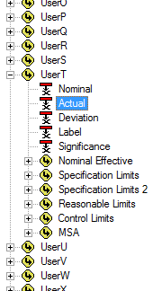
Change the association to Feature>Characteristics>UserT>Actual.
Show/Hide ScreenshotShow/Hide Screenshot
Click Ok.
Click Ok.
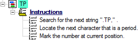
Locate the Instructions node under "TP".
Change the first instruction string to ".TP,".
Step 29: Review Results of Yoke Actuals
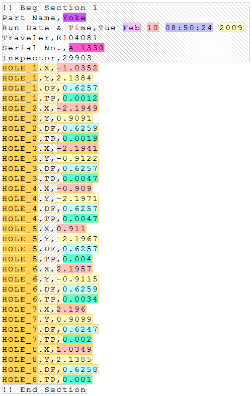
Below are screen captures of what the file highlighting and the grid in DataSmith will look like once all of the steps have been completed for the Yoke Actuals configuration. Compare the screen captures to your finished results to confirm that all of the steps were completed successfully.
The file should now look like this:
Show/Hide ScreenshotShow/Hide Screenshot
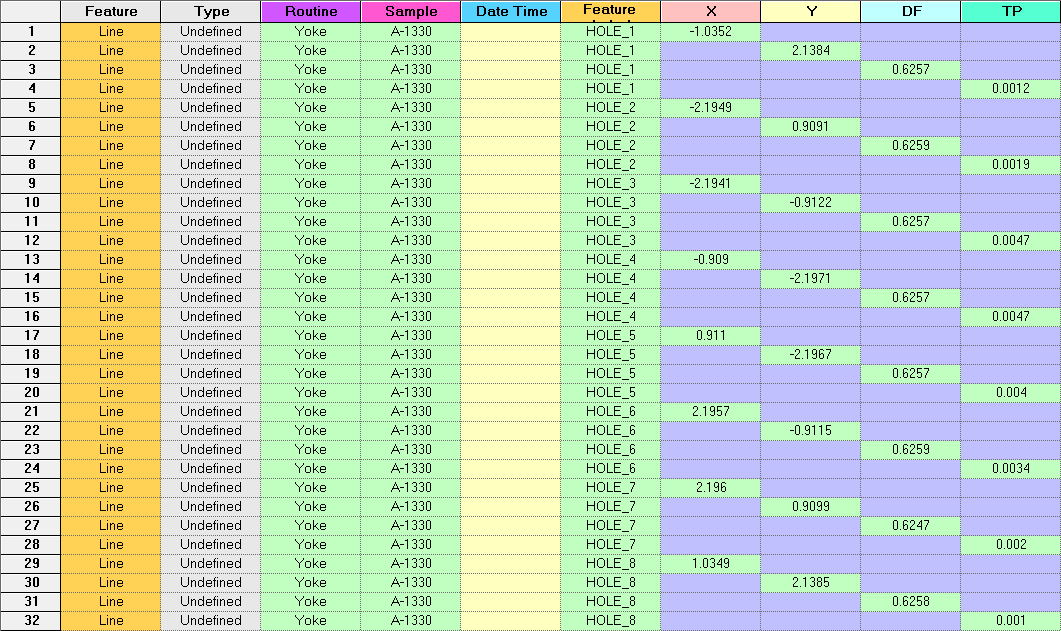
Switch the main window from the Yoke-1330.csv tab to the Grid tab.
The grid should look like this:
Show/Hide ScreenshotShow/Hide Screenshot
You have reached the end of the Yoke Tutorial, and are now ready to read the Yoke data into your Database!