In this section we will highlight four components. The components will be added to the two views which will eventually be used in two separate steps of the inspection. These are divided as shown below. Click the name to see the location:
| ATS Bike Frame | ATS Bike Brakes |
|
Cross Bar
|
Brake Cable (Front)
|
|
Down Tube
|
Brake Pad(Back)
|
ATS Bike Frame
We will start by defining the cross bar.
Select the ATS Bike Frame view.

Select the Design tab in the ribbon.
Click Add Component. Alternatively, you can right click on the layer in the View Explorer and select Add Component from the context menu that appears.
The part and location selection window opens.
Select Bike Parts in the Part Folder drop down list. This will limit the list to the parts you created.
Select Cross Bar and click OK.
In the next window disable Use Fill and click OK.
Moving Around the View
Before you start drawing the component shape you will want to zoom into the right location.
Move the mouse over the middle of the cross bar and hold down the right mouse button. Now you can drag the view so that the cross bar is in the middle of the screen.
Roll the mouse wheel forward to zoom in so that the cross bar fills the view.
You can also move around the view and zoom in and out while you're drawing the component.
Draw the Component
You can now draw the component shape. The default setting will allow you to draw a shape using lines and curves.
Click on the view where you want the edge of the component to begin.
You now have the option to draw a line or a curve. By default it will draw a line.
You can switch to drawing a curve by pressing the Tab key or the C key. Switch back to drawing a line by pressing the Tab key again or the L key.
Click at the next point along the edge of the component.
If you selected to draw a curve you can now create the curve by moving the curve handles.
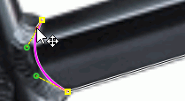
Keep drawing around the edge of the component.
When are get close to the starting point again, press the F2 key or double-click on the starting point.
The component is created and listed in the View Explorer.
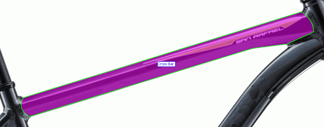
If you want to modify a completed component select the relevant shape icon in the View Explorer and click Edit in the Design menu.

Repeat the steps to add the Down tube.
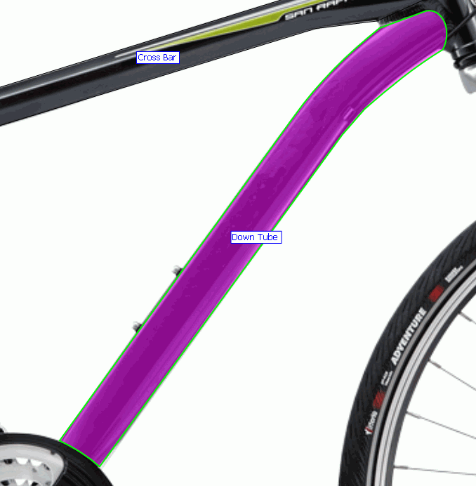
Save and close the ATS Bike Frame view.
ATS Bike Brakes
Select the ATS Bike Brakes view.
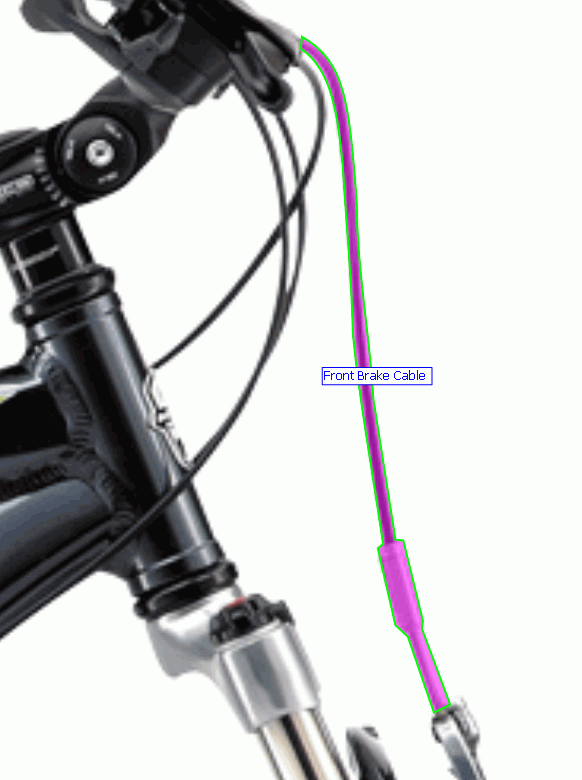
Add the Front Brake Cable using the steps described above.
When selecting the part/location you will need to expand Brake Cable and select Front.

The finished component should look like the following:
Add the Back Brake Pad using the steps described above. To start with we'll just outline half of the brake pad.
It should look like the following:
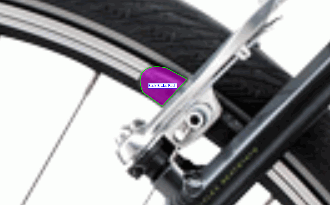
Now we can add the other half.
Select the component in the View Explorer.

Click Add Shape in the Design tab of the ribbon.
Outline the other half of the brake pad as described above.
The finished component should look like the following:
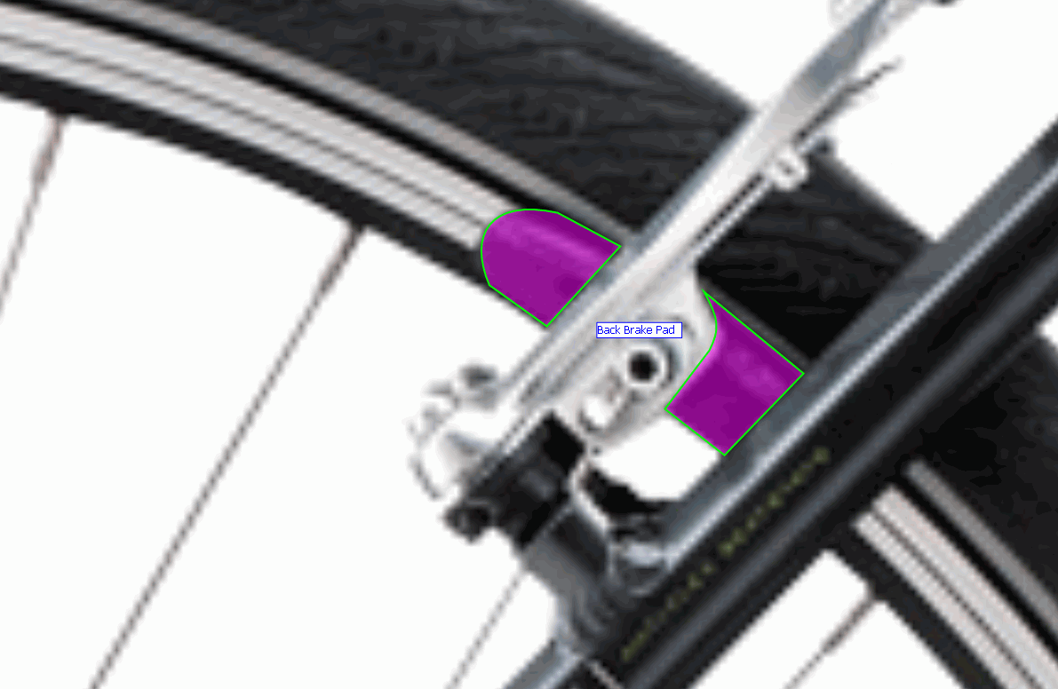
Obviously some of the brake pad is hidden behind other components. This can be dealt with using a layered view. However, we won't be looking at that in this tutorial.