In this topic: Hide
You can configure ATS SPC to work your way by means of the Options property pages. Choose Tools+Options to see them.
Each tab opens a page of configuration options that you can set.
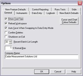
Show Tool Tips Check this box to have ATS SPC show you a small explanation window when the mouse cursor hovers over a toolbar button.
Reload Workspace Check this box to have ATS SPC reload, each time it starts up, the batches that were open when you last closed it down. Uncheck it to have ATS SPC start with no batches open.
Auto Save… Check this box to have ATS SPC automatically save any changes you have made when you swap from Design Mode to Data Entry Mode. If you uncheck this box ATS SPC will ask if you want to save.
Confirm Deletes Check this box to have ATS SPC ask for confirmation each time you delete a batch, feature, or measurement set.
Recent Batch List Length Enter the number of batches you want ATS SPC to remember in the most recently used batch list in the File menu. Note that any changes you make here will take effect next time you start ATS SPC.
Normal Bias When ATS SPC performs capability studies it is usual for it to be a little biased towards the normal distribution since this is the most straight forward distribution to handle statistically. ATS SPC will only recommend a non-normal distribution if it is significantly better a fit than the normal. Enter here the percentage bias. If you enter ‘1’ here then ATS SPC will recommend a non-normal distribution only if its regression coefficient is at least 1% higher than that for the normal distribution.
Company Name Enter here your company or department name as you would like it to appear in print-out headers and footers etc.
Control Defaults Press this button to open a colour selection dialog to choose default colours for chart controls and cursor controls in batch views.
There are two ways to auto-start ATS SPC when Windows starts…
Include ATS SPC in the Startup menu…
1. Right click the Windows Start button and from the context menu choose Explore.
2. In the left hand pane of the Explorer window double click the Programs item (or click the small '+' sign next to it) to open the Programs menu.
3. Double click the ATS item to open the ATS menu in the right hand pane. (Note that if you installed ATS SPC into a program group other than ATS, you should open that menu item here instead.)
4. Drag the ATS SPC item from the right hand pane on to the Startup item in the tree view in the left hand pane. Hold down the Control key while you drop ATS SPC into the Startup menu to make a copy of it rather than just move the original.
Next time you start your computer ATS SPC will start automatically as soon as Windows has finished loading.
Make ATS SPC the System Shell
This method is not for the faint hearted and should be used only if you want your system to run ATS SPC and nothing else. The Windows 'shell' is the program you use to control Windows and to run other programs. Normally Explorer is the shell and this gives you the ability to look through files on your hard disk, manage printers and other devices attached to your computer and, via the task bar and start menu, launch other programs. If you make ATS SPC the shell you will have none of these facilities. Your computer will run ATS SPC and that is all! You must remember to set ATS SPC to shut down Windows when you close it or you will have to do it via the task Manager (press CTRL+ALT+DEL)!
To make ATS SPC act as the shell you must edit the file, System.Ini, in the Windows folder. You can use the Notepad to do this.
1. Launch the Notepad and open C:\Windows\System.Ini (or use the name of the Windows folder on your computer if it is not called C:\Windows).
2. Find the heading [Boot], and under that find the line shell=Explorer.Exe.
3. Insert a semi-colon in front of the word 'shell' and then add a new line underneath…
shell=C:\Program Files\ATS\ATS SPC\ATS SPC.Exe
Substitute the correct folder name if you installed ATS SPC to folder other than C:\Program Files\ATS\ATS SPC.
4. Save the file.
5. Restart your computer. Windows will load, as will any device drivers and virus checking software, but there will be no task bar, and no Start button, only ATS SPC.
6. Remember to set ATS SPC to close down Windows when you exit (Tools, Options, General tab).
Make Explorer the System Shell Again
If you want to stop using ATS SPC as the shell you must edit the System.Ini file again…
1. Close down the computer and restart it.
2. Press F8 while the computer is starting up and, from the start up menu; choose 'Command Prompt only'. This will run MS-DOS rather than Windows.
3. Launch the MS-DOS editor, Edit.Exe, and open the C:\Windows\System.Ini file…
Edit C:\Windows\System.Ini
4. Find the [Boot] section and remove the semi-colon from the original shell line and insert one, instead, in front of the shell=C:\…\ATS SPC.Exe line. Save the file.
5. Restart your computer, allowing it to load Windows normally this time.
Update Rate ATS SPC receives updated measurement data from the instruments at this interval. If you set it too slow your cursors will be slow and jerky. If you set it too fast your computer will spend too much time processing instrument data and ATS SPC and other applications will be un-responsive. A good compromise is around 50 to 200ms.
The optimum speed will depend on your instruments. Some, including many hand held RS232 based callipers, update slowly – about 4 times per second (250ms). Others, such as quadrature-based scales and analog probes, update rapidly and may justify an update time of less than 100ms
You can specify the update rate either by typing in a number of milli-seconds or by moving the slider control with the mouse.
Confirm Reset Check this box to have ATS SPC ask for confirmation before resetting your measuring instruments. This can be useful in preventing accidental resets.
Allow Reset when Out of Range Normally ATS SPC will not allow you to reset or calibrate any instruments that are showing an error or out of range condition. Check this box to over-ride this safeguard.
Always Active Normally ATS SPC turns off instruments when they are not needed, e.g. those in inactive measurement sets, but some instruments reset themselves when turned on again. . Check this box to keep the instruments turned on all the time and prevent unwanted resets.
Reset Tolerance This feature is intended to protect your measuring instruments from accidental or erroneous resetting – perhaps using the wrong reset master. The value here is the tolerance (in measuring units) about the current reset position in which ATS SPC will allow an instrument to be reset.
For example – if an instrument is measuring in millimetres and you set the Reset Tolerance to 0.05, then try to reset the instrument when it is reading, say 0.060mm, ATS SPC will show a warning message. You can still reset the instrument if you want but ATS SPC warns you that there may be a problem.
Use a value of 0.0 effectively to turn off reset protection - ATS SPC will allow resetting no matter how far from the previous reset.
Calibration Tolerance This feature protects your instruments against erroneous calibration. The value is a percentage difference allowable between the new resolution value and the previous one.
For example - if you set this value to 0.5, recalibrate an instrument with a resolution value of 0.010, and the new resolution value is less than 0.0095 (0.010 - 0.5%) or greater than 0.0105 (0.010 + 0.5%), ATS SPC will show a warning message. You can still accept the calibration if you want but ATS SPC warns you that there may be a problem.
Use a value of 0.0 effectively to turn off calibration protection - ATS SPC will allow calibration no matter how different the new resolution is from the previous value.
Accept/Reject Range ATS SPC applies a feasibility test to data when you formally enter it and will refuse data which is grossly too big or too small. The reject criterion is based on the tolerance band and you can determine how many tolerance bands ATS SPC should accept.
The number here is the range of acceptable data – in tolerance bands. It is always centered on the centre of the tolerance band. Thus, 1 means just the tolerance band itself, while 3 means the tolerance band and one bandwidth outside each limit. A figure of 0.5 would mean one quarter of the tolerance band either side of the tolerance centre value.
You can specify the feasibility band either by typing in a number or by moving the slider control with the mouse.
Reject Action Here you determine what ATS SPC does if it rejects the data. Choose an action from the drop down list box.
1. Accept Anything: ATS SPC makes no feasibility checks and will enter any value.
2. Beep and Wait: If the value to be entered is beyond the acceptance range ATS SPC will not enter it but will play the data entry reject sound (if configured) and will wait for you to re-try the same measurement(s).
3. Beep and Skip: If the value to be entered is beyond the acceptance range ATS SPC will not enter it but will play the data entry reject sound (if configured), skip the measurement(s), and move on to the next feature or set.
4. Ask and Wait: If the value to be entered is beyond the acceptance range ATS SPC will not enter it but will open a dialog asking if you want to enter it or not. If you decline ATS SPC will wait for you to re-try the same measurement(s).
5. Ask and Skip: If the value to be entered is beyond the acceptance range ATS SPC will not enter it but will open a dialog asking if you want to enter it or not. If you decline ATS SPC will skip the measurement(s) and move on to the next feature or set.
Show In Control Report Check this box to have ATS SPC stop at the end of a subgroup and show a message box if the subgroup is in control.
Show Out of Control Report Check this box to have ATS SPC stop at the end of a subgroup and show a message box if the subgroup is out of control.
Save Control Reports If you check this box ATS SPC will save control reports until after you have finished all measurement sets. If you leave the box unchecked ATS SPC will show control reports immediately each set is entered (which may result in several reports).
Enable Data Tagging Check this box to tag, or categorise, each item of data as you enter it. See Data Tags for more details.
Prompt on Batch Open Check this box if you want ATS SPC to remind you to select the data tags to use each time you open a batch in data entry view.
Use Game Buttons Check this box to use your computer’s game port buttons for data entry and instrument reset etc. Button 1 is used for data entry, and button 2 for instrument reset.
Flash on Data Entry Check this box to have ATS SPC give you a visible confirmation of data entry by flashing one of the controls in the batch view. The top most control in the tab order flashes – see Control Order, Sequence, and Buttons for details about tab order.
When you enter a message into the logbook ATS SPC offers a list of pre-defined messages to save you (or your operators) a bit of typing. This is where you enter the list of messages as you want it to appear.
Force Logbook Message when Out of Control Check this box to ensure that operators always make a logbook entry if an out of control condition occurs. When a batch goes out of control ATS SPC will not allow further data entry until a logbook message is entered. Remember, however, that ATS SPC does not make any checks on the contents of the message entered and there is nothing to stop an operator from entering a blank or nonsense message just to get off the hook!
Force Logbook Message on Elimination Check this box to ensure that operators always make a logbook entry if they eliminate (or uneliminate) a subgroup or reading.
1. Click New.
2. In the edit control that appears, type in your message.
3. Use the cursor keys to go back and make corrections if necessary.
4. Press ENTER or click outside the message region to finish your message.
1. Click the message you want to edit and then click on Edit, or click twice slowly (not a double click) on the message.
2. Click the mouse where you want to add or delete characters or use the cursor keys.
3. Press DEL to delete characters or type in new ones.
4. Press ENTER or click outside the message region to finish your changes, or press [Escape] to abandon your changes and revert to the original message.
1. Click on the message you want to delete.
2. Press DEL or click the Delete button.
When you create a new batch ATS SPC gives it some properties by default. You can save yourself time by ensuring that the defaults are suitable for you.
The configuration options do not affect batches that already exist. To change existing batches you must edit the batch plan dialog page Batch Properties (available in Design Mode only).
Subgroup Size How many measurement values per subgroup. One subgroup is one chart point. Range: 2 – 25.
20 Day Equivalent Some values or actions are valid only for processes that have been in control for at least 20 days. To make things easy for ATS SPC this is the number of subgroups that you would normally enter in 20 days of production
Example: One subgroup per hour for one 8 hour shift per day gives 160 subgroups in 20 days
Capability Target What is your minimum acceptable value for capability indices (i.e. Cp, Cpk, Pp, Ppk etc.). This is sometimes expressed as a working number of standard deviations.
Since Cp & Pp are calculated from the width of +/- 3 standard deviations,
a target Cp or Pp of 1 is equivalent to working to 3 standard deviations. For
each additional std dev. Add 0.33 to the target index – so…
4 Std Dev = 1.33
5 Std Dev = 1.67
6 Std Dev = 2.00 etc. etc.
Scene Grid To help align controls in the batch view ATS SPC can display a grid. Any controls you place in a scene align and size themselves to the grid. These options determine the appearance of the grid and its spacing.
Scene Colours When you add new scenes to a batch view they will start life with these default colours. New scenes may be transparent, may be coloured like other windows on your computer, or may have default colours of their own. The sample scene tab in the dialog shows what your choice will look like.
Later you can change the colours and other properties of any scene individually using the Scene Properties dialog available in design mode.
When you create a new feature, either by inserting one into a batch or by creating a new batch, it starts life with some default properties. You can save yourself time by configuring them to be suitable for the way you work.
This page is similar to the batch plan dialog page: Feature Properties
The control switches determine which conditions ATS SPC considers to be ‘out of control’. Violations can be reported in the out of control report dialog at the end of each subgroup – the ‘Subgroup’ column, or as highlighted points in the chart – the ‘Chart’ column.
Certain violations are not too relevant to the charts. Tolerance limit violations for instance have no statistical significance in a mean/sigma chart so you might clear the chart boxes for tolerance limits but check the subgroup boxes. You still want to be told about them!
These switches set defaults used when creating new features but you can change the control switch settings for each feature of an existing batch in the Control Switches dialog available in design mode.
1. Choose Tools+Options from the menu to open the Configuration Options property pages.
2. Select the Control Switches tab.
3. Check the boxes to indicate which types of violation you want ATS SPC to report.
Check the box in the ‘chart’ column to have the violation indicated as a highlighted point in the chart, or the ‘subgroup’ column to have it reported in a pop-up message box as you are measuring.
4. Clear the boxes for the violations you want ATS SPC to ignore.
If you check or clear a box set into a frame you check or clear all the boxes below it inside the frame.
5. When you have finished press the OK button or move to another tab to save your changes.
This refers to a collection of tests that ATS SPC performs on your process data in addition to looking for simple limit violations.
The trend tests apply simple rules of probability to determine if your data is suitably random in nature or is being influenced in some way – perhaps by a special cause variation that you have not yet identified. The rules that you configure here are applied to new batches as you create them, but they have no effect on existing batches. If you create a batch from an existing batch (a template) the new batch will have the same runs test rules as the template batch.
Runs Above and Below the Mean A run of 7 chart points above or 7 below the mean is highly unlikely if the data is random in nature. In coin tossing terms it’s as likely as 7 heads or 7 tails in succession. ATS SPC identifies such runs in your charts and can flag them as control violations. The default value of 7 follows the guide-lines from the 'big three' motor manufacturers QS9000 standard.
Drifting Upwards or Downwards A sequence of 7 consecutive chart points all progressively higher or lower than the previous one (i.e. 7 gaps between 8 points) is also about as likely as 7 heads or 7 tails in a row. The default value of 7 follows the guide-lines from the 'big three' motor manufacturers QS9000 standard.
Middle Third Typically, data in a process control chart will be normally distributed so most of the points will be near the middle of the chart with progressively fewer at the extremes. Since the control limits represent the expected range of the data in any chart, if ATS SPC finds significantly more or less than two thirds of the data in the middle one third of the control limit band it reports a violation. Hence: ‘middle third rule’. The default values of 40% and 92% follow the guide-lines from the 'big three' motor manufacturers QS9000 standard. If the middle third roll size is 25, will result in an out of control condition if 23 or more out of any 25 subgroups are within the middle third or if 8 or less out of any 25 are outside the middle third.
1. Choose Tools+Options from the menu to open the Configuration Options property pages.
2. Select the Trend Tests tab.
3. Type or dial in the number of consecutive points to constitute a runs failure (default: 7).
4. Type or dial in the number of consecutive gaps to constitute a drift failure (default: 7).
5. Type or dial in the maximum and minimum allowable percentages of chart points in the middle third region (defaults: 92% and 40% respectively).
6. Type or dial in the number of subgroups to consider when assessing the middle third test (default 25).
ATS SPC assesses rolling groups of this many chart points and counts the percentage of points inside and outside the middle third region between the control limits. E.g. subgroup 25 is highlighted if 1-25 have more than 23 (92% of 25) or less than 10 (40% of 25) points in the middle third. Subgroup 26 is flagged if 2-26… etc.
7. Press the OK button or move to another tab to save your changes.
The changes that you make will apply to new batches created from now on but will not affect existing batches.
All ATS interface cards have some digital input and output lines, known as the ‘Standard I/O’, as well as instrument inputs, and you can use these to send signals to other systems, or commands to ATS SPC from other systems. PLC based factory automation systems, for example, might send a data entry signal to ATS SPC after loading a part into a measurement fixture, and will wait for ATS SPC to signal that is has completed the measurement before unloading it again..
A PLC toggling a Standard In Line has a similar effect to you pressing a key. Typically a system will be configured so that a single StdIn line will represent a key.
Take care with voltage levels - PLCs typically work at 24Vdc but the StdIO uses 5V computer logic levels and can be damaged by 24V signals!
As installed the Standard I/O lines have the following functions…
Standard In bits
StdIn lines should be held high and dropped low for the following functions
0 Enter Data (dropping this input low is equivalent to pressing F4)
1 Reset Instruments (=F2)
2 Delete Last (=F3)
The remaining bits, 3-7, are unconfigured.
Standard Out bits
StdOut lines are normally low and go high to signal the following events…
0 Ready - high when ATS SPC is able to accept a data entry signal
1 Error - normally low, high if something goes wrong
2 Inst OOT - (Instantaneous Out Of Tolerance) high if the current set has live measurements outside the tolerance limits, low if all features are in tolerance. This line responds to live cursor values.
3 EOS - (End Of Subgroup) goes high after the last measurement in a subgroup has been entered. Stays high until the next data entry
4 OOT - (Out Of Tolerance) Goes high after an out of tolerance measurement is entered. Goes low again after the next data entry if all features in the set are in tolerance.
5 OOC - (Out Of Control) Goes high after an out of control measurement is entered. Goes low again after the next data entry if all features in the set are in control.
6 First Set - High when the measurement sequence returns to the first set (or feature). Goes low after the next data entry if there is more than one set.
7 StdIn Acknowledge - Goes high when a StdIn command is received, and low again when the StdIn returns to the quiescent state (all lines high).
The Standard Out functions are fixed, but the Standard In lines can be re-configured, using the StdIn page of the Options dialog, to represent other ATS SPC key commands. In more complex systems a combination of lines can represent a key to give you up to 255 different keys.
Translate using this file
ATS SPC saves these StdIn mappings as a text file and will prompt you for a file pathname when you need to save them. Type in a name or browse to a convenient folder. Windows convention is that you should save such files to the ‘My Documents’ folder, or to a sub-folder of My Documents, ‘My Documents\ATS\ATS SPC’ for example.
Mappings
Each StdIn mapping starts with a number from 0-254. This is the binary number given by the StdIn bits that remain high. Pulling bit 0 low, for example, will leave bits 1-7 high, which represents 254, or 0xFE in hexadecimal.
This number is followed by the name of the key that want to represent. The StdIn Mapping page has a list box with all the key names that you can use but most of these are intuitive anyway. The default mappings look like this…
254 F4 ;
bit 0, enter data
253 F2 ;
bit 1, reset instruments
251 F3 ;
bit 2, delete last
The lines shown above all have a comment explaining what they mean. Comments begin with a semi-colon, ‘;’, or an asterisk, ‘*’, and ATS SPC ignores them. They are there purely as a reminder to you about what the mapping does.
Mapping Errors
When you make changes to the mappings, ATS SPC checks them and highlights any errors by colouring the offending text. For example, a number above 254 is not representable by the 8 StdIn lines so, if you entered an extra character by mistake, say ‘2544’, ATS SPC would flag an error by colouring the ‘2544’. If you choose not to select key names from the list box but type in an invalid name, say you enter ‘254 F45’, then ATS SPC will highlight the invalid name, ‘F45’. You must correct the errors before saving your new mappings.
Enable StdIn
By default, StdIn is disabled to prevent open Standard I/O ports from generating spurious signals. If you want to use StdIn to control ATS SPC you must enable it by checking this box.