In this Topic Hide
Create Trust Between UA Server, UA Client and LDS
Configure the OPC UA Server to trust the LDS
Configure the LDS to trust the OPC UA Server
Configure the OPC UA Server to trust ATS Bus
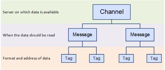
OPC Client Channels are used to create named connections to the shop floor via an OPC Server. These connections are called tags. In order to create a tag you need to specify the server on which the data exists, the format of the data, when the data should be read and the address of the data.
This information is specified in different layers as shown below where the channel contains messages which contain the tags:
ATS Bus can handle OPC connections using either the more recent OPC Unified Architecture (UA) specifications or the legacy OPC Data Access (DA) specifications.
In order to use OPC DA specification the OPC Browsing Service must be installed. See here.
The OT bus stop must be installed on the same system as the OPC DA server because the OPC channels do not support remote OPC servers.
ATS Bus Cockpit queries the OPC DA server through the ATS Bus Data Service which relays the ‘queries’ to a service named OPC Browsing Service. This service is available as a separate installer and should be installed on the same host as where the OPC Server is installed. The OPC Browsing Service invokes OpcEnum (an OPC foundation OPC server enumerator) to query the available OPC servers on that host.

One of the advantages of OPC UA specification is that the OT Bus Stop can be installed on a separate host to the OPC UA server.
A Local Discovery Server (LDS) is optional, but the OPC UA Channel can query an OPC UA endpoint directly without using a LDS.
A trust has to be setup between the LDS and OPC UA Server and the OPC UA Server and the OT Bus Stop OPC UA channel. For information on how to do this see here.
1. Select the OT Bus Stop tab.
2. Click OPC Channels.
A list of the existing OPC channels is shown.
3. Click Add.
A new window opens.
4. Enter a name for the channel.
The name of the channel must be unique within the entire ATS Bus configuration.
5. Select Data Access in the OPC Specification drop-down list.
6. Enter the Browsing Host. This is the hostname of the computer that hosts the OPC Browsing Service.
7. Enter the Browsing Port. This is the port where the browsing service listens.
8. Enter the OPC Server Host. This is the hostname of the computer that is running the OPC Server.
9. Click Refresh to update the list of OPC servers.
10. Select the OPC Server from the drop-down list.
11. If required, enable Reconnect to the OPC server if keepalive messages are missing for more than the configured interval and specify an interval in minutes. If there is no response from OPC server for time longer than the specified interval then reconnection is started. If the server does not support keepalive or you don’t want this behavior simply uncheck the option.
12. Enter a description in the default language and any other required languages.
13. Add channel messages as described below.
4. Enter a name for the channel.
The name of the channel must be unique within the entire ATS Bus configuration.
5. Select Unified Architecture in the OPC Specification drop-down list.
6. Select a Discovery mode. This can be either
o Use Local Discovery Server: Use when local discovery server is available.
o Use Endpoint Discovery: Use for direct OPC Server endpoint selection.
7. Enter the host and port of either the Local Discovery Server (LDS) or the OPC Server. By default the LDS service is on port 4840.
8. Click Refresh to update the list of servers.
9. A dialog asking to trust the OPC Server may appear. Click Yes if you trust the server.
10. Select the OPC Server from the drop-down list.
You must log on to the OPC UA Server machine and
trust the client application named ‘ATS Bus OPC UA Client’. This certificate
is installed when selecting Yes
in the previous step.
You must also logon to the OPC UA Server machine and trust a second
client application named ‘ATS Bus OPC UA Client’, when starting an
OT bus stop.
11. Enter an Endpoint Address. Endpoints specify which security policy is used for communication (signing and encryption).
12. If the Check domain checkbox is ticked, then the domain in the certificate must match the one provided in the OPC endpoint.
13. The Username and Password are used to log on to an OPC server using a user name and password. The OPC UA client will logon as an anonymous user if a user name and password are not provided.
14. Enter a description in the default language and any other required languages.
15. Add channel messages as described below.
Message Definitions must be created before channel messages can be created.
Channel messages can be created once an OPC channel has been defined.
1. While editing an OPC Channel select the Channel Messages tab.
All existing channel messages contained in the channel are listed. The table shows the name of the channel message, the direction in which the message is going and whether or not the message is currently active.
Messages are Uploaded towards the Bus and Downloaded away from it.
2. Click Add.
3. Enter a name for the channel message.
The name of the channel message must be unique within the entire ATS Bus configuration.
4. Select a Message definition. Message Definitions act as templates when adding messages to a Channel. They specify whether the message is being uploaded from equipment or downloaded to equipment and also list the different data fields that will be available in the message.
The Tags control opens. In the right-hand pane it lists the fields contained within the message. The left-hand pane lists tags that will be created that match those fields.
If the field has an Index value associated to it this will be added to the end of the tag name. For example, if the field name is _OperatorID and the field index is Extract then the tag name will be _OperatorID_Extract.
5. If you don't want tags to be created automatically disable Create remaining tags for message fields.
6. Use the arrows on the right-hand side to re-order the fields. To refresh the list of tags to match it disable and enable Create remaining tags.
7. If required, enable Generated tags include data source.
8. Click Save. You are returned to the New Channel Message window.
9. Select an Acquisition Type. This will define how frequently the channel message is read. The following options are available:
o Interval Acquisition (upload only): The values of the tags are read at a given time interval given in seconds.
o Trigger Tag Acquisition: The values of the tags are read when the selected trigger tag changes value.
o On Change Acquisition (upload only): The values of the tags are read when they change value.
10. Select the required Acquisition Settings.
11. Select the Acquisition type and its settings as follows:
Upload
o Interval acquisition: Acquisition
defined in seconds. The interval must be provided. You can also
enable Message filtering
and click  to decide whether a channel message
should be processed. The message filter requires 2 operands and an operator
to create a condition. The channel message is processed when the condition
evaluates to ‘true’.
to decide whether a channel message
should be processed. The message filter requires 2 operands and an operator
to create a condition. The channel message is processed when the condition
evaluates to ‘true’.
The Data type specifies the type of data (Boolean, Integer) that the operands will use. The left and right operand can use the following data sources:
• The actual value from the PLC
• Constant value
• Data translation table
• Function evaluation
• Bus stop variable
The operator can be:
• Less than ‘<’
• Less than or equal ‘<=’
• Equals ‘==’
• Not equal ‘<>’
• Greater than or equal ‘>=’
• Greater than ‘>’
o Trigger Tag Acquisition: The values of the tags are read when the selected trigger tag changes value. The trigger tags can be specified using the ‘Acquisition settings’.
§ Simple handshake upload: Apply a simple handshake using a trigger tag.
§ Double handshake upload: Apply a double handshake using a trigger tag and acknowledge tag.
§ Rising edge: Start message exchange when the trigger tag goes from zero to non-zero.
§ Falling edge: Start message exchange when the trigger tag goes from non-zero to zero.
o On Change Acquisition: The values of the tags are read when one of the tags in the channel message changes value. This acquisition type does not have additional configuration settings.
Download
o Trigger Tag Acquisition: The values of the tags are downloaded to the PLC using a handshake. The handshake prevents the channel from downloading new values to the PLC if the trigger is not in an idle state. The trigger tags can be specified using the ‘Acquisition settings’.
§ Value download: This downloads the channel message directly to the PLC without using a handshake.
§ Simple handshake download: Apply a single handshake when downloading the data to the PLC.
§ Double handshake download: Apply a double handshake when downloading to the PLC using a trigger tag and acknowledge tag.
For more information on acquisition settings see here.
12. If required, enable Handshake Only. This should be selected if the message is to be used for a heartbeat interface.
13. Enable Active so that the channel message can be used.
The tags provide the link to the location of the data on the server.
14. Click Add below the Tags pane (or Edit to modify an existing tag).
A new window opens.
15. Enter the name of the tag in the Description field.
16. Select a Data Type. This is the format in which the data will be received (e.g. Integer, Text, Char, etc.).
17. Enable the Active checkbox to ensure the tag is active.
18. If required, enable Mandatory. If a message is received and a mandatory tag doesn't have a value then the message won't be processed.
The source and destination can now be selected. The source and destination will depend on whether it is an Upload or Download message definition.
19. Select the Data
source and the additional information the data source requires.
This can be one of the following:
Name |
Description |
Required Information |
OPC access path (upload only) |
The value is read from an OPC data source. |
Enter the OPC data source. This can be entered manually
or you can click the search button ( |
Constant value |
The tag will always be the same value. |
Enter the value to be used. |
Data Translation table |
The value is read from an OPC data source and then translated using a data translation table. |
Select the translation table to use and the access path for the source value that will be translated. |
Function evaluation |
The value is read from an OPC data source and then modified using a function. |
Enter the function to use and the access path for the source value that will be modified by the function. |
Reset counter evaluation |
Instead of sending the received value it sends the iteration. For example, if the last known value was 50 and it receives a value of 53 then the output will be 3. |
No extra information required. |
Rollover counter evaluation |
Instead of sending the received value it sends the iteration. As soon as a defined limit is reached the value is reset and the counter goes back to zero. For example, if the current value is 99, rollover is set to 100 and 5 is the incoming value then the result is 6. This is calculated as follows: (100 – 99 + 5 = 6) |
Set the rollover value set for the equipment the value is being received from. |
Bus Stop Variable |
|
|
20. Select the Destination.
This will either be a Bus Stop variable
(for download) or a Message field
(for upload). The tag is added to the channel message.
21. Click OK.
The channel message is added to the channel.
22. Click OK.
The channel is saved.
In order to use the LDS (Local Discovery Server), the OPC UA Server and LDS should trust each other. This is done by using certificates.
The following steps are required to have a Kepware OPC UA Server trust the LDS:
1. Open the Kepware OPC UA Configuration manager.
2. Go to the Discovery Servers tab.
3. Click Import….
4. Select C:\ProgramData\OPC Foundation\UA\Discovery\pki\own\ualdscert.der and click Open.
5. Click Close.
If the certificate file is not present in that location then first perform the following steps:
6. Open the Microsoft Management Console by entering mmc.exe in a dos console.
7. Select File > Add or remove Snap-in (or press Ctrl+M)
8. Select Certificates from the Available snap-ins and click Add.
9. Select Computer account and click Next.
10. Select Local Computer and click Finish.
11. Click Ok
12. Go to Console Root > Certificates (Local Computer) > UA Applications > Certificates.
13. Right-click on the Certificates leaf under UA Applications in the left hand side pane and select All tasks > Import.
14. Click Next.
15. Click Browse.
16. Locate and open the ualdscert.der file that you were trying to import in step 4. You may need to change the file type to All files (*.*).
17. Click Next.
18. Select Place all certificates in the following store and click Browse.
19. Select UA Applications and click OK.
20. Click Next.
21. Click Finish.
22. Restart the OPC server.
23. Run the Kepware OPC UA Configuration Manager.
24. Select the Discovery Servers tab.
25. Click Import….
26. Locate and select the exported certificate file.
27. Click Open.
28. Click Close.
The first step in this process is to export the Server instance certificate to a file, the following steps are required:
1. Run the Kepware OPC UA Configuration Manager.
2. Select the Instance Certificates tab.
3. Click Export server certificate….
4. Enter a filename and click Save.
5. Click Close.
6. Open the Microsoft Management Console by entering mmc.exe in a dos console.
7. Select File > Add or remove Snap-in (or press Ctrl+M)
8. Select Certificates from the Available snap-ins and click Add.
9. Select Computer account and click Next.
10. Select Local Computer and click Finish.
11. Click Ok
12. Go to Console Root > Certificates (Local Computer) > UA Applications > Certificates.
13. Right-click on the Certificates leaf under UA Applications in the left hand side pane and select All Tasks > Import.
14. Click Next.
15. Click Browse.
16. Select the file that has been saved. You may need to change the file type to All files (*.*).
17. Click Next.
18. Select Place all certificates in the following store and click Browse.
19. Select UA Applications and click Ok.
20. Click Next.
21. Click Finish.
All listed clients need to be trusted in the OPC UA Server configuration. The steps will vary depending on the software used. The following steps are for Kepware.
1. Open the OPC UA Configuration application.
2. Select the Trusted Clients tab.
3. Right-click on the untrusted ATS Bus OPC UA Client and select Trust.
The OPC UA client requires endpoints to communicate with the OPC UA Server.
1. Run the Kepware OPC UA Configuration Manager.
2. Select the Server Endpoints tab.
3. Click Add….
4. Change the settings according to your requirements and click Ok.
The selected port (49320 in the example above) must be open in the Windows firewall.
5. Click Close.
ATS Bus OPC UA Client certificate is used for the low level connection between ATS Bus and the OPC UA server
Obtaining timestamp of a data change event in the OPC, MTConnect and PLC channel.
The PLC, MTConnect, OPC client and OPC server channels can expose a timestamp to specific message field class types that shows when the data on the device (or OPC Server) has changed:
o Property attribute with its name set to “Timestamp” (case sensitive)
o EquipmentCondition – EquipmentStateTimestamp.
o EquipmentCondition – EquipmentModeTimestamp.
An OPC channel message (direction = upload) is triggered on change and it is configured to obtain the data from multiple OPC tags (Tag1 and Tag2). The following message definition can be used to obtain the tag value and the time it changed its value:
Direction = Upload
o A ‘Property’ with its name set to “MyTag1”
o A ‘PropertyAttribute’ with its name set to “Timestamp” (case sensitive) and its index set to “MyTag1”
o A ‘Property’ with its name set to “MyTag2”
o A ‘PropertyAttribute’ with its name set to “Timestamp” (case sensitive) and its index set to “MyTag2”
The message definition should be used (linked) with an OPC channel message:
o A tag named “Tag1” linked to message field ‘MyTag1’ and having access path ‘/my/OPC/Access/Path/To/Tag1’ will give the tag value.
o A tag named “Tag1_Timestamp” linked to message field ‘Timestamp - MyTag1’ and having access path ‘/my/OPC/Access/Path/To/Tag1’ will give the timestamp of when the Tag1 changed its value.
o A tag named “Tag2” linked to message field ‘MyTag2’ and having access path ‘/my/OPC/Access/Path/To/Tag2’ will give the tag value.
o A tag named “Tag2_Timestamp” linked to message field ‘Timestamp - MyTag2’ and having access path ‘/my/OPC/Access/Path/To/Tag2’ will give the timestamp of when the Tag2 changed its value.
The channel message implementation reads the timestamp instead of the tag value when the classtype of the message field named ‘Timestamp’ is set to ‘PropertyAttribute’.
When published on the bus, the channel message data will translate to the following B2MML:
<SegmentData>
<ID> Tag1</ID>
<Value>
<ValueString>tag value of Tag1</ValueString>
</Value>
<Value>
<ValueString>The tag value of Tag1_Timestamp</ValueString>
<Key>Tag1_Timestamp</Key>
</Value>
</SegmentData>
<SegmentData>
<ID> Tag2</ID>
<Value>
<ValueString>tag value of Tag2</ValueString>
</Value>
<Value>
<ValueString>The tag value of Tag2_Timestamp</ValueString>
<Key>Tag2_Timestamp</Key>
</Value>
</SegmentData>
An OPC channel message (direction = upload) is triggered on change and it provides the Equipment state. The following message definition can be used to obtain the equipment state (tag value) and the time the state changed (when the tag changed its value):
o Direction = Upload
o A ‘EquipmentContext’ with its name set to ‘EquipmentId’ and its index set to “state1”
o A ‘EquipmentCondition’ with its name set to ‘EquipmentState’ and its index set to “state1”
o A ‘EquipmentCondition’ with its name set to ‘EquipmentStateTimestamp’ and its index set to “state1”
The message definition should be used (linked) with an OPC channel message:
o A tag named “MyEquipmentId” linked to message field ‘EquipmentId – state1’ and having access path ‘/my/OPC/Access/Path/To/Tag3’ will give the tag value.
o A tag named “MyEquipmentState” linked to message field ‘EquipmentState – state1’ and having access path ‘/my/OPC/Access/Path/To/Tag1’ will give the tag value.
o A tag named “MyEquipmentState_Timestamp” linked to message field ‘EquipmentStateTimestamp – state1’ and having access path ‘/my/OPC/Access/Path/To/Tag1’ will give the timestamp of when the Tag1 changed its value.
The channel message implementation reads the timestamp instead of the tag value when the classtype of the message field named ‘EquipmentStateTimestamp’ is set to ‘EquipmentCondition’.
When published on the bus, the channel message data will translate to the following B2MML:
<EquipmentActual>
<EquipmentID>MyEquipmentId</EquipmentID>
<Description>state1</Description>
<EquipmentActualProperty>
<ID>EquipmentState</ID>
<Value>
<ValueString>Value of MyEquipmentState</ValueString>
<Key />
</Value>
<Value>
<ValueString>Value of MyEquipmentState_Timestamp</ValueString>
<Key>Timestamp</Key>
</Value>
</EquipmentActualProperty>
</EquipmentActual>
 ) to
locate it. In the
) to
locate it. In the