) button on the Alignment toolbar) provides for the definition of the alignment setup. In addition, two buttons are provided to assist in setup verification: Check Setup and Test Run.
In this topic: Hide
The CM4D Alignment Module provides functionality to simulate a CMM inspection to a datum scheme using data collected to a different scheme. The data for the features defining the new datum scheme must have been collected with the original data. A new alignment is computed using the original measurement data for the datum features, then the data for the remaining features is recomputed to the new alignment. The new measurement data is computed by re-projecting the surface points onto the surface as though the CMM inspection actually took place, using the new alignment as a reference frame. Hole features are moved in 3D space accordingly. Constructed features are also recomputed using the new data.
A typical scenario of use for this type of alignment centers on the inspection of a body-in-white. The body can be inspected in its entirety relative to the primary datum scheme for the body. Without the use of CM4Ds alignment functionality, each of the openings (e.g., doors, windows, hood, deck lid, and lamps) may be inspected separately with its own datum scheme. The CM4D alignment module allows the body to be inspected only once, and then subsets of data can be analyzed using software to simulate alignment to individual datum schemes.
It is also possible within the CM4D alignment module to enter offsets to the datum characteristics to perform predictive analysis. The reference system is re-computed using the offsets, and then all of the measurement data for the features is re-computed and made available for analysis and reporting. Offsets are not saved to the database with the alignment definition.
Feature definition (e.g., labels and nominals) is derived from the source routine, as is the measurement data. The spec limits, however, can be uniquely assigned and used during the alignment process.
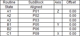
1. Alignment definition: An alignment requires six datum characteristics to be defined.
2. A list of Features to align: Once the alignment has been calculated, these features will have their measurement values recomputed for each new alignment.
1. Load the Source Routine(s).
2. Create a Subroutine that includes all of the Features to be aligned, including all features containing the six datum characteristics. Reference Features for Constructed Features must also be included in the Subroutine.
3. Define the alignment.
4. Enable the alignment by toggling the alignment on.
See the Simple Block Alignment Tutorial for detailed instructions on using Alignment.
The Alignment Properties dialog (opened using the Alignment Properties () button on the Alignment toolbar) provides for the definition of the alignment setup. In addition, two buttons are provided to assist in setup verification: Check Setup and Test Run.
Selecting the Check Setup button will cause all entries in the dialog to be saved and then verified for completeness. A cursory check will be made to see if the information provided is “reasonable”. If all conditions are deemed reasonable, 'OK' will be returned in the dialog. The conditions checked for successful alignment are as follows:
· All entries are made in the setup dialog.
· All features provided are valid types for alignment purposes.
· The axis definitions are not duplicated.
· The three A datum features define a valid plane (not co-linear).
· The three A datum features are not concentric.
· The axis defined matches the axis of the plane that the three A datum features form (this is only a warning – it is possible that this could happen under certain circumstances).
· The two B datum features are not concentric.
· The line passing through the features for B1 and B2 is not parallel to the axis specified as B (this is a warning only – it is possible that this could happen under certain circumstances).
Selecting the Test Run button will cause all entries in the dialog to be saved and then an actual alignment is computed. In addition to performing and alignment and computing new data, a dialog is presented with the result of the alignment. If the Detailed Test Report check box is “on”, an extensive log of information is collected and presented upon completion of the alignment.
· Alignments can only be used on Subroutines.
· Spec Limits assigned directly to Subroutine Features are only used when the alignment mode is on.
· When alignment mode is on, any Samples that fail to align will contain no data.
· Only one subroutine can be activated in a query at one time.
· Subroutines can be created using features from more than one routine.
· Subroutines can have constructed features created directly in them using reference features from the source routines. These constructed features can be used for alignment datum, as in the case of midpoints.
· Offsets can be provided for each datum. The values provided are added to the nominal characteristic for purposes of calculating the alignment. This is used to experiment with changes (e.g., shims, nominal changes). The offsets are only used during run time. They are not saved to the database or with the document.
|
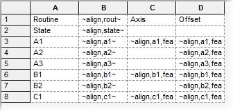
Variables in a Table |
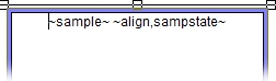
Variables in a Text Box |
|
Unresolved Variables |
|
|
|
|
|
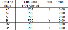
Resolved Variables with Alignment Mode OFF |
|
|
|
|
|
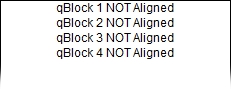
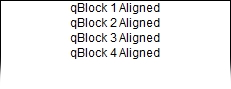
Resolved Variables with Alignment Mode ON |
|
|
|
|
|
|