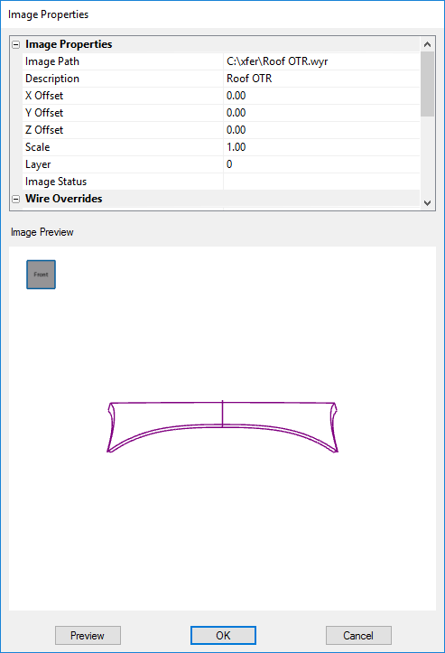
Image Properties
The Image Properties dialog is the hub for all modifiable properties of an image within CM4D. Image Properties are the same for both Routine Images and Document Images. The only difference is how the dialog is accessed:
Routine Images - Open the Image Tab of the Routine Properties dialog and click either Add Image or Modify Image.
Document Images - Right click the main Document Image node of the Images Tab and select Properties from the context menu.
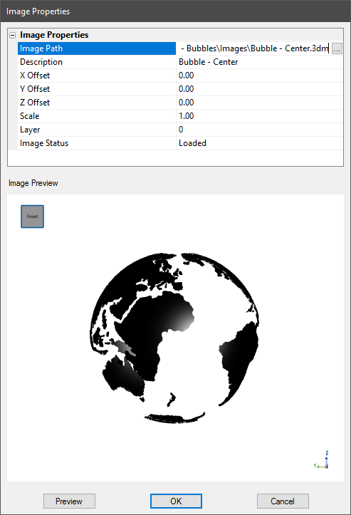 Image Path
The Image Path is the directory location where the image file is stored. This path can be a local directory, a mapped drive, or a UNC path. Click in the Image Path field and then click the ![]() button to browse to an image location. See also, Supported 3D File Types.
button to browse to an image location. See also, Supported 3D File Types.
Description
Enter a description for the model. The text entered in this field can also be used with Image Layer Filters.
Offsets
An Offset allows one image to be set off from another image within the View relative to the axis defined. Offsets may be used for "crossover" parts. Offsets do not apply to 2D images.
Offset X - The distance the image is moved from near [-] to far [+] on the X axis.
Offset Y - The distance the image is moved from right [-] to left [+] on the Y axis.
Offset Z - The distance the image is moved from up [-] to down [+] on the Z axis.
The same front door may be used for both Car A and Car B, but on Car B the door is set 30mm back on the body than it is on Car A. In order to be able to use one image file for both Car A and Car B, offsets will allow the Front Door image file to be "offset" 30mm on the X axis from the original position.
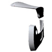
No OffsetNo Offset
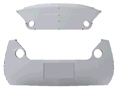
Offset on the Z axis of -500mm (Oriented to YZ-Behind)Offset on the Z axis of -500mm (Oriented to YZ-Behind)
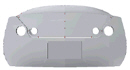
Offset on the Z axis of -500mm (Rotated to a side view)Offset on the Z axis of -500mm (Rotated to a side view)
Scale
Scale refers to the scale of the image relative to the original image size defined in the image file. Scale may be used when the ratio of an image does not correspond with the data the image is associated with. This must be a positive number. Scale does not apply to 2D images.
Layer
Assign a layer number (0-99) to the image.
For wireframe images, this must be the same number as the Layer Override set in the Wire Properties section of this dialog. The layer number is then selected on a View to show this image. See here for more information on View Layers.
Image Status
The Image Status will indicate if an image has been Loaded from the Database, or is Not Loaded.
Image Preview
Click Preview to load a preview of the model. For 3D images, the model can be zoomed or rotated using either the mouse controls or the Orientation Cube in the upper left corner.
Wireframe Overrides
 Wireframe Overrides are available once a wireframe image file is selected in the image path. Wireframes are loaded into CM4D with certain properties assigned to the image file when it was created. Some of these properties can be overridden using options set in the CM4D image properties.
To enable a wire override, select the check box and pick an option from the corresponding dropdown.
Status Override
Set the status of the wireframe image.
- Active -
- Live -
- Masked -
- Hidden -
- Deleted -
Color Override
Apply a color to the entire wireframe. This color overwrites any assigned colors within the wire file. Available colors are the standard CM4D Colors. See here for the list.
Style Override
Apply a line style to the entire wireframe.
|
Style |
Example |
|
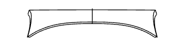
Solid |
|
|
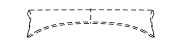
Dashed |
|
|
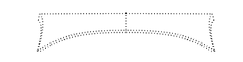
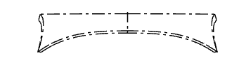
Phantom |
|
|
Centerline |
|
Layer Override
A wireframe may be created with layer numbers assigned to various parts of the whole frame. The Layer Override may be used to assign a single layer number to the loaded wireframe image file. This setting will override any individual layer assignments coded in the wireframe file.
Assign a layer number (0-99) to the wireframe image. This must be the same number as the Layer set in the Image Properties section of this dialog. The layer number is then selected on a View to show this wire image. See here for more information on View Layers.
Hand Override
Show only the set hand of the wireframe image, when handedness is set in the wire model file.
- None - Ignores any handedness set in the wireframe.
- Both - Displays both the Right and Left sides of the wireframe.
- Left - Displays only the Left side of the wireframe.
- Right - Displays only the Right side of the wireframe.
- Other -
Wireframes with a handedness of Both (either as an override or set in the file) can utilize an additional setting at the View level, where you may choose either Right or Left only. See the topic View Layer Tab for options related to the Both handedness.
Thickness Override
The thickness is an integer value which represents the size of the wire lines. This value represents millimeters (mm). If the document is set to inches (IN), the line size will be converted automatically from MM to IN.
Can we improve this topic?