Constructed Features
Constructed Features are features that are fabricated by CM4D using derived Features as Reference Features. These calculated features can have any feature characteristics. The type is not derived based on characteristics like they are for the standard features in CM4D, but rather the type is determined by the feature type assigned. Constructed features can be created manually in CM4D or with a DataSmith translator.
Some Constructed features have a unique 3D marker assigned. Hover over an image below to identify which feature type it represents:
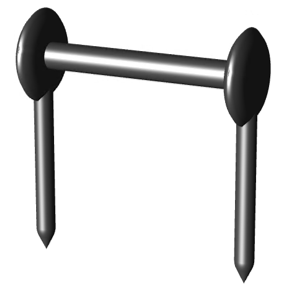 |
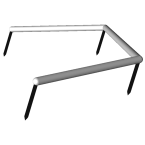
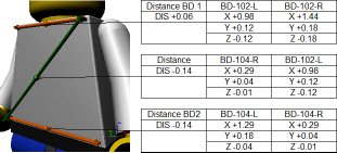
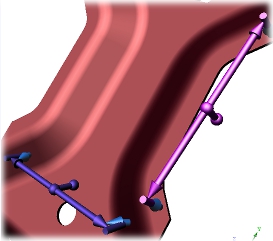
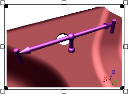
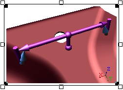
Distance The calculated distance between two reference points. |
 |
Midpoint The calculated middle point or mean value between two reference points. |
 |
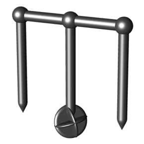
Range A series of two or more points in sequence representing the values of the reference feature points. |
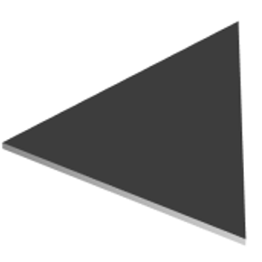 |
Plane A plane area constructed from three reference points. The three reference feature points make up the vertices of the plane marker. |
DistanceThe calculated distance between two reference points. |
MidpointThe calculated middle point or mean value between two reference points. |
RangeA series of two or more points in sequence representing the values of the reference feature points. |
PlaneA plane area constructed from three reference points. The three reference feature points make up the vertices of the plane marker. |
At times the marker position may be obstructed by the model or other feature markers. Small adjustments can be made by going to the Feature Properties and setting a Spin or Length to the marker for the selected feature.
Constructed Feature Type Rules
Constructed features are not automatically typed by CM4D from the characteristics present like it is with Derived Features (Surface, Hole, etc.). The type must be specified when added to the database, either through DataSmith or CM4D.
| Type | Default Characteristics |
| Distance | Distance |
| Midpoint | XYZ |
| Plane | XYZ, IJK |
| Polar | Polar |
| Range | |
| Reference | XYZ |
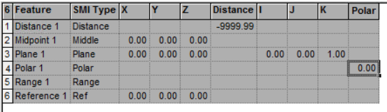
Constructed features created in CM4D are given the required nominal characteristics by default.
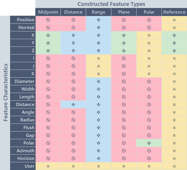
In special cases, additional characteristics may be added manually according to the matrix below:

Constructed Features in Sift Rules
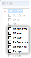
The Constructed Feature types are selected in the Sift Rules dialog the same as any of the derived feature types, including specific characteristics. If you want to include the Reference features for any of the constructed features, either in a DataSet or the markers on a View, enable the option 'Add Rows for Reference Features' in the Show/Hide section of the Sift Rules.
Constructed Feature Markers
View-Level Feature Marker Properties
To change the markers properties on the View, go to the View Properties. On the View tab, click Markers in the bottom right portion of the dialog. All changes made in the Feature Marker Properties dialog will apply to all of the feature markers for that type throughout the View, and will be saved at the document level. See here for details on the View Marker Properties.
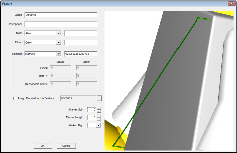
Feature-Level Feature Markers
To change the marker for an individual Feature, find the Feature in the Data Tree. Right click the Feature label and select Properties. An alternative method is to change this value manually using DataUtility, but you must know the specific values needed as there is no visual interface for the marker properties in DataUtility. All changes made in the Feature Properties dialog will apply to the feature marker for the selected feature ONLY, and will be saved to the Database as a property of the selected feature.
Using Feature Level Properties can help to differentiate features from one another within the same View.
Midpoint
A Midpoint feature is the calculated middle point or mean value between two reference points.A Midpoint feature is represented in a view by a unique marker that consists of extension lines and a dimension line with rounded ends.
| Default Midpoint Feature Marker without Augment Reference Features | Default Midpoint Feature Marker with Augment Reference Features |
 |
 |
The Midpoint feature marker Material (color/texture), extension length, and thickness (Marker Width) may be modified either per View (vie the View Annot Properties) or per Feature (via the Feature Properties dialog).
Plane
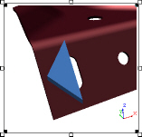
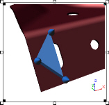
A Plane feature is a calculated feature representing the plane created by three features.APlane may be used as a Reference feature for other Constructed Feature types, such as Distance. A Plane feature is represented in a view by a unique triangular feature marker. The three Reference Features which create the Plane make up the vertices of the feature marker.
| Without Augment Reference Features | With Augment Reference Features |
 |
 |
The Plane feature marker Material (color/texture) and thickness (Marker Width) may be modified either per View (via the View Annot Properties) or per Feature (via the Feature Properties dialog).
Distance
A Distance feature is the calculated distance between two reference points. It can also have Normal, Polar, Azimuth, Horizon or User characteristics.A Distance feature is represented by a marker that consists of lines extending from the reference points and a dimension line linking the two reference points.
| Without Augment Reference Features | With Augment Reference Features |
 |
 |
The Distance feature marker Material (color/texture), extension length, and thickness (Marker Width) may be modified either per View (via the View Annot Properties) or per Feature (via the Feature Properties dialog).
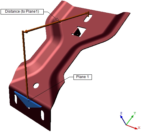
Distance to Plane
When a Distance feature uses a Plane feature as one of the two required Reference features, the distance feature marker is adjusted so that the extension lines point to the center of the plane.
Feature marker behavior when a Distance feature references a Plane feature.
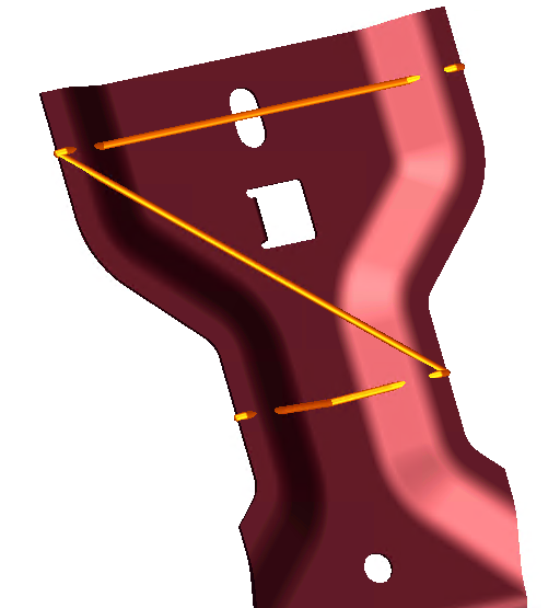
Range
A Range a Constructed feature created by CM4D that is the calculated range of values for the assigned Constructed Reference features. The Range feature will be given the same Characteristics as each of its Reference Features.
Range Feature Markers
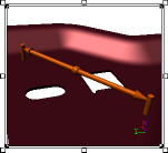
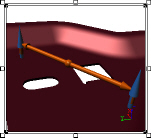
The Range feature marker is an orange line with tapered ends. The Range marker color and thickness (Marker Width) may be modified either per View (via the View Annot Properties) or per Feature (via the Feature Properties dialog).
| Without Augment Reference Features | With Augment Reference Features |
 |
Range Variables
The following variables are available for calculating statistics on Range features:
| Variable | Returns: |
| ~rstat,count~ | The number of Range features that are in the DataSet. |
| ~rstat,mean~ | The mean value of the range of deviations. |
| ~rstat,hi~ | The highest value in the range of deviations. |
| ~rstat,lo~ | The lowest value in the range of deviations. |
| ~rstat,stddev~ | The standard deviation within the range of deviations. |
| ~rstat,ppk~ | The Ppk value of the range of deviations. |
Polar
A Polar Feature is a feature that is designated as a Constructed Polar and fits the criteria specified in the table in the topic Feature. The Polar type is a Constructed feature created by CM4D that has a Polar characteristic and represents the Miniball radius of the selected Reference features.
See the topic Polar Charts for more information on Polar features and Miniball.
Reference
A Reference Featureis a feature that is designated as a Reference and fits the criteria specified in the table in the topic Feature. The Reference type is a non-inspected feature point whose measurement values always have a deviation of zero.
See also:
Can we improve this topic?