Classic Toolbars
3D Toolbar
|
Icon |
Name |
Description |
|||
|
|
Edit View |
Always enabled. Toggles Edit Mode on and off. Must be activated to manipulate the 3D model (3D orientation, Feature selection, display mode and cutting planes) in the View. |
|||
|
|
Select Features |
|
Enabled when View is in Edit Mode. Click on a Feature marker to select the Feature. If a Feature is already selected, it is deselected and the new Feature is selected. Click on a selected Feature marker to deselect the Feature. |
||
|
|
+ |
|
Hold the Ctrl key and click on a Feature marker to add successive Features to the selected Features list. Click on a selected Feature marker to deselect the Feature and remove it from the list. |
||
|
|
Select Features by Area |
|
Enabled when View is in Edit Mode. Click and drag a bounding box around Feature markers to select Features and add them to the Selected Features list. If any Features are already selected, these are cleared from the list before the newly selected Features create the new list. |
||
|
|
+ |
|
Hold the Ctrl key, then click and drag a bounding box around Feature markers to select Features and add them to the Selected Features list. If any Features are already selected, the newly selected Features are added to the current list. |
||
|
|
Push Selected Features |
Enabled when at least one Feature marker is selected in the View. Opens the Selected Features List. You can push the selected feature(s) to DataSource, Subroutine or Reference. |
|||
|
|
Clear Selected Features |
Enabled when at least one Feature marker is selected in the View. Clears all Selected Features from the list. All feature maker highlights are removed. |
|||
|
|
Zoom Fit |
Always enabled. Sets the zoom of the View to fit the entire part (loaded Feature markers and 3D model) within the View. |
|||
|
|
Zoom Box |
Enabled when View is in Edit Mode. Click and drag a bounding box to zoom in on an area of the 3D image. |
|||
|
|
Camera |
Always enabled. Opens the Camera dialog to save information about the placement of a 3D image within a view. See here for more information on Cameras. |
|||


Align Toolbar
|
Icon |
Name |
Description |
|
|
Align Left |
All selected annotation are aligned based on the left edge |
|
|
Align Right |
All selected annotation are aligned based on the right edge |
|
|
Align Bottom |
All selected annotation are aligned based on the bottom edge |
|
|
Align Top |
All selected annotation are aligned based on the top edge |
|
|
Align Vertical |
Lines up the annotation in the direction of the Y axis, moving along the axis as their centers are aligned |
|
|
Align Horizontal |
Lines up the annotation in the direction of the X axis, moving along the axis as their centers are aligned |
|
|
Space Horizontally |
All selected annotation are spaced horizontally based on the size of the annotation |
|
|
Space Vertically |
All selected annotation are spaced vertically based on the size of the annotation |
|
|
Same Width |
Resizes all selected annotation to an average width |
|
|
Same Height |
Resizes all selected annotation to an average height |
|
|
Same Size |
Resizes all selected annotation to an average width and height, making them the same size |
|
|
Mirror Horizontally |
Selected annotation are mirrored horizontally |
|
|
Mirror Vertically |
Selected annotation are mirrored vertically |


Alignment Toolbar
To toggle alignment on and off in CM4D click Toggle Alignment in the toolbar. To view the Alignment properties of the active subroutine, click Alignment Properties. Click the drop down arrow to select a new subroutine from the list.
|
Icon |
Name |
Description |
|
|
Toggle Alignment |
Toggles alignment on and off |
|
|
Alignment Properties |
Opens the alignment properties dialog |
|
|
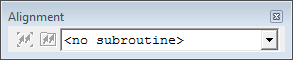
<no subroutine> |
Select a Subroutine from the dropdown menu. |


Examples:
Toolbar without an active subroutineToolbar without an active subroutine
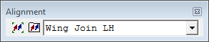
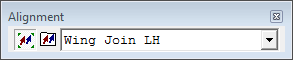
Toolbar with active subroutine and alignment mode onToolbar with active subroutine and alignment mode on
Annot Toolbar
Icon |
Name |
Description |
|
Edit Sheet |
Default selection tool |
|
Assign Annot DataSource w/ Drag |
Assigns a DataSource to an annotation just by clicking and dragging a feature onto the annotation you want the data assigned to |
|
Edit Leader w/ Tool |
Allows you to change a leader just by clicking on the annotation whose leader you want to change and dragging the cursor to the point where you want the leader to end |
|
New Text |
Creates a new Text annotation |
|
New View |
Creates a new View annotation |
|
New Chart |
Creates a new Chart annotation |
|
New Table |
Creates a new Table annotation |
|
New Line |
Creates a new Line annotation |
|
New Shape |
Creates a new Shape annotation |
|
New Container |
Creates a new Container annotation (deprecated) |
|
New Picture |
Creates a new Picture annotation |
|
New Graph |
Creates a new Graph annotation |
|
New Plot Space |
Add a plot space to an existing chart while it is in edit mode. To add a plot space, double click on the chart to put it into edit mode, then click the new plot space button and draw a box within the chart where you want the new plot space. See also, Chart Plot Space. |
|
New View Axes |
Creates a new view axes within a view annotation while it is in edit mode. This tool is only enabled for use with Views using old Visualization. |
|
New Group |
Creates an empty group that can have annotation added to it by placing it in edit mode and creating new annotation inside it. To group existing annot, select all of the annot you want to group together, then right-click and choose Group from the context menu. |
|
Execute Tool |
When the Execute tool is active and clicked on an annotation, it executes any action set in the Execute Action section of the Annot Properties General Tab. This may link to another page, shrink the annot, or execute a selected Script. |
|
Zoom Tool |
Zooms the viewing area of your page by clicking the zoom tool and drawing a box around the area you want to zoom |
Cutting Plane Toolbar
|
Icon |
Name |
Description |
|
|
|
Toggle X Plane |
Toggles the cutting plane along the X axis on/off. |
|
|
|
|
Invert X Plane |
Enabled when the X plane is active. Flips the cutting plane to cut the geometry in the opposite direction along the X axis. |
|
|
Toggle Y Plane |
Toggles the cutting plane along the Y axis on/off. |
|
|
|
|
Invert Y Plane |
Enabled when the Y plane is active. Flips the cutting plane to cut the geometry in the opposite direction along the Y axis. |
|
|
Toggle Z Plane |
Toggles the cutting plane along the Z axis on/off. |
|
|
|
|
Invert Z Plane |
Enabled when the Z plane is active. Flips the cutting plane to cut the geometry in the opposite direction along the Z axis. |
|
|
Show/Hide Planes |
Enabled when at least one cutting plane is active. Toggles the visibility of the cutting plane bounding box. By default, the cutting plane reference box is visible. While the plane is hidden, it cannot be moved. |
|
|
|
Toggle Quadrants |
Enabled when two or more planes are active. Toggles the cutting planes from a single cutting section to separate cutting sections.
|
|
|
|
Cap Sections |
Caps the cutting plane, leaving a 'slice' appearance. Replaces the old CM4D "section thickness". Not yet implemented. The 3D HOOPS engine has built-in interactive cutting plane support and automatically generates “capping geometry” for closed meshes. It also supports aggregating cutting planes into sectioning planes to slice through and cut-out parts of a model. |
|
|
|
Reset |
Enabled when at least one cutting plane is active. Sets all cutting plane locations to default and turns off all cutting planes. |
|


Display Mode Toolbar
|
Icon |
Name |
Description |
|
|
Shaded |
[Default Mode] Sets the rendering mode to Phong Shading. Colors are obtained from the CAD file. This mode displays the model geometry as shaded and opaque. |
|
|
Shaded with Lines |
Sets the rendering mode to Phong Shading with Lines. This mode displays the model geometry as shaded and opaque, with the addition of visible, unobscured lines. Colors are obtained from the CAD file. This is essentially a combination of the Shaded and Hidden Lines modes. This mode may display some parts better than just Shaded. |
|
|
Hidden Lines |
Sets the rendering mode to Fast Hidden Line. This mode displays only visible, unobscured lines. Faces of visible geometry are used to obscure the lines in the model. All color defined in the CAD file is turned white. This mode is a simple view that may provide a better result for hardcopy or screenshots. The Transparency option in the View properties is ignored when this mode is set. |
|
|
X-Ray |
Sets the rendering mode to X-Ray. This mode displays the model geometry as semi-transparent, but not the feature markers. This mode allows you to see through a complex scene to view or select the Feature markers. The Transparency option in the View properties is not ignored when this mode is set. |


Edit Toolbar
|
Icon |
Name |
Description |
|
|
Delete |
Deletes current selection |
|
|
Cut |
Cuts your selection and places it on the clipboard to be pasted to another location on the current sheet, or another sheet or document |
|
|
Copy |
Copies your selection to the clipboard to be pasted to another location on the current sheet, or another sheet or document |
|
|
Paste |
Pastes object or text from clipboard to current sheet |


File Toolbar
|
Icon |
Name |
Description |
|
|
New |
Starts a new CM4D document |
|
|
Open |
Opens an existing CM4D document |
|
|
Open Managed Document |
Opens the Select Managed Document dialog that was formerly only accessible by right-clicking the DataSource icon in the tree bar and selecting Open Managed Document from the menu |
|
|
Save |
Saves the current document; if it has not been previously saved, the Save As dialog will appear |
LogEditors Toolbar
|
Icon |
Name |
Description |
|
|
Feature Properties |
Opens the Feature Properties dialog |
|
|
Feature Editor |
Opens the Feature Editor dialog |
|
|
Process Control |
Opens the Process Control Editor dialog |
|
|
MSA Wizard |
Opens the Measurement Statistical Analysis Wizard |
|
|
Log Viewer |
Opens the Process Change Log Viewer |
|
|
Logging Enabled |
Turns Process Change Logging on |
|
|
Logging Disabled |
Turns Process Change Logging off |


Print Toolbar
|
Icon |
Name |
Description |
|
|
|
Prints your active document as per your Print Setup dialog |
|
|
Export Data |
Opens the Export Data dialog |
|
|
Email Sheet |
Sends your active sheet to an E-mail as a PDF attachment. This option only works if you have an E-mail client installed on your computer. |


Report Toolbar
|
Icon |
Name |
Description |
|
|
Toggle |
Toggles ReportTweak mode on and off |
|
|
Activate |
Creates or activates a ReportTweak report from the selected annotation |
|
|
Add |
Adds any missing annotation to the ReportTweak report |
|
|
Clean |
Deletes duplicate (blue) or invalid (red) annotation |
|
|
Analysis |
Opens the Tweak Analysis dialog, which supplies information about all annotation in the ReportTweak report |
View Toolbar
|
Icon |
Name |
Description |
|
|
Toggle Tree Bar |
Hides or restores the Tree bar to the User Interface |
|
|
Toggle Info Bar |
Hides or restores the Info bar to the User Interface |
Zoom Toolbar
|
Icon |
Name |
Description |
|
|
Zoom In |
Increases the current sheet display scale incrementally with each click |
|
|
Zoom Out |
Decreases the current sheet display scale incrementally with each click |
|
|
Zoom 100% |
Zooms the sheet as close to a one-to-one ratio as the display will allow |
|
|
Zoom Fit |
Makes the sheet fit in your document area |
|
|
Zoom Selected |
Zoom in on a selected annotation |
|
|
Zoom Scale |
Allows you to choose at what scale you want to view your annotation on the sheet |
|
|
Redraw |
Repaints the entire display with all of the current information in the document region |


If you hold the ctrl key and click Zoom Fit when in the array sheet, the sheet with the selected annotation will be zoom fitted to the view region; if no annotation is selected, if you have an Active Sheet, then the active sheet will be fitted to the view region.
Can we improve this topic?