Cutting Planes
Cutting planes are used to hide geometry on one side of a plane. One or more cutting planes can be added to the model to create a View that shows only part of the model. The X, Y and Z axis planes can be used in an AND/OR function. Markers for the Features located on the part of the model 'cut' out are removed from the view if the cutting plane excludes the center point of the marker. When enabled, the cutting plane boundary sizes automatically adjust to fit within the bounding box of the model. The cutting planes have the option to show or hide the outline of the plane, but while the plane is hidden it cannot be moved.
|
The view must be in Edit Mode to activate the Cutting Plane toolbar. Once you exit Edit Mode, the View retains the cutting plane settings.
Select one of the three planes to initialize the plane for that axis. Select the Invert button next to one of the three planes to invert the cutting plane on that axis. Active buttons are highlighted with a blue background. Set cutting planes are retained until the Reset button is applied. Any cut geometry is retained while the model is rotated, moved or zoomed. Clicking the opposite button turns off one state and enables the other. For example, click the X Plane to turn on the cutting plane on the X axis. Next, click the invert button next to the X plane icon. Note that the highlight is removed from the X plane icon and is now highlighting the invert button. Click the X plane button again to turn off the cutting plane. Click the X plane button to reactivate the cutting plane, |
|
See also, Set a Cutting Plane.
|
|
|
|
|
|
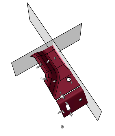
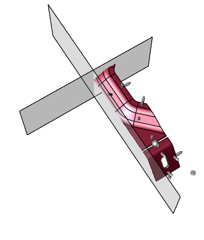
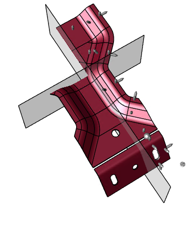
Plane X & Plane Y |
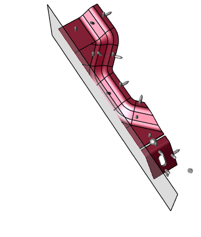
Plane X Inverted |
Plane X Inverted & Plane Y |
Plane X Inverted & Plane Y + Toggle Quadrants |
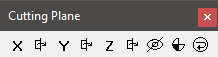
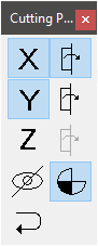
Cutting Plane Toolbar
The Cutting Plane toolbar has controls for adding and removing cutting planes. Set cutting planes are retained until the Reset button is applied. Exiting View Edit Mode hides the cutting plane but retains any cut geometry.
|
Icon |
Name |
Description |
|
|
|
Toggle X Plane |
Toggles the cutting plane along the X axis on/off. |
|
|
|
|
Invert X Plane |
Enabled when the X plane is active. Flips the cutting plane to cut the geometry in the opposite direction along the X axis. |
|
|
Toggle Y Plane |
Toggles the cutting plane along the Y axis on/off. |
|
|
|
|
Invert Y Plane |
Enabled when the Y plane is active. Flips the cutting plane to cut the geometry in the opposite direction along the Y axis. |
|
|
Toggle Z Plane |
Toggles the cutting plane along the Z axis on/off. |
|
|
|
|
Invert Z Plane |
Enabled when the Z plane is active. Flips the cutting plane to cut the geometry in the opposite direction along the Z axis. |
|
|
Show/Hide Planes |
Enabled when at least one cutting plane is active. Toggles the visibility of the cutting plane bounding box. By default, the cutting plane reference box is visible. While the plane is hidden, it cannot be moved. |
|
|
|
Toggle Quadrants |
Enabled when two or more planes are active. Toggles the cutting planes from a single cutting section to separate cutting sections.
|
|
|
|
Cap Sections |
Caps the cutting plane, leaving a 'slice' appearance. Replaces the old CM4D "section thickness". Not yet implemented. The 3D HOOPS engine has built-in interactive cutting plane support and automatically generates “capping geometry” for closed meshes. It also supports aggregating cutting planes into sectioning planes to slice through and cut-out parts of a model. |
|
|
|
Reset |
Enabled when at least one cutting plane is active. Sets all cutting plane locations to default and turns off all cutting planes. |
|


Toggle Quadrants
 The toggle quadrants button moves all the active cutting planes to the same cutting section. This option is only available if there are at least two cutting planes active.
Show/Hide Cutting Plane
 The transparent plane with a bold border represents the active cutting plane. The bounding box is displayed while the cutting plane is active, but can be hidden when you are done setting the cut plane. While the plane is hidden, it cannot be moved.
Can we improve this topic?