3D Models in CM4D
About 3D Models in CM4D
Data in CM4D is associated dynamically with a 3D product model to visually link actual measurement data with nominal design data. Models can be associated either to data via the Routine, or to a document and assigned to a View. CAD models are directly supported in CM4D using the HOOPS Exchange technology. See here for information on supported image file types.
3D Model Controls
A 3D model in a report can be moved within the View to provide the best orientation to represent the loaded data. The model can be oriented during the application session to focus on certain features, isolate data points or select data from markers on the model.
The tools and controls that are used to manipulate the 3D model are dependent on the state of the view - if the View is in Edit Mode or not. While a View is in Edit Mode, the 3D Toolbar has additional buttons for selecting Feature markers. The mouse buttons and scroll wheel (at times in conjunction with the keyboard) are used to rotate, zoom or select feature markers.
The 3D model can be moved within the view using Orient, Zoom and/or Cameras functions described below.
Rotate the Model
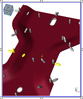
3D models can be rotated freely within a View by dragging the model with the mouse. You may want to spin or rotate a model in order to see certain Features or to select Features that are not prominently displayed. The position of the model may be saved as a Camera along with the zoom.
View in Edit Mode ( ):
):
- Click on the model and drag the cursor in the desired direction
Orient the Model
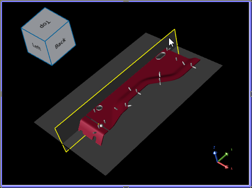
The View context menu Orient can be used to set the View to one of the six standard orthogonal orientations: Top (XY), Bottom (YX), Back (YZ), Front (ZY), Right (XZ) and Left (ZX).
View in Edit Mode ():
- Use the Orientation Cube
View not in Edit Mode:
- Right-click on a view and select Orient > Top from the context menu
- Right-click on a view and select Orient > Bottom from the context menu
- Right-click on a view and select Orient > Back from the context menu
- Right-click on a view and select Orient > Front from the context menu
- Right-click on a view and select Orient > Left from the context menu
- Right-click on a view and select Orient > Right from the context menu
Zoom the Model
Views loaded with 3D models and 3D Feature marker data can be zoomed in, out or to the maximum size that fits the part within the view border. The Zoom state of a View may be saved as part of a Camera along with the orientation.
Zoom In
Zoom In decreases the distance between the viewer and the part. Detail is increased; less of the entire loaded model is visible.
View in Edit Mode ():
- Scroll the mouse wheel forward to zoom in
- Scroll the mouse wheel backward to zoom out
View not in Edit Mode:
- Right-click on a view and select Zoom > In from the context menu
Zoom Out
Zoom Out increases the distance between the viewer and the part. Detail is reduced; more of the entire loaded model is visible.
View in Edit Mode ():
- Scroll the mouse wheel forward to zoom in
- Scroll the mouse wheel backward to zoom out
View not in Edit Mode:
- Right-click on a view and select Zoom > Out from the context menu
Zoom Max
Zoom Max immediately sets the zoom distance on the View that fits all loaded parts (model and Feature markers) within the view boundary.
View in Edit Mode ():
- Click on the surface of the CM4D View Orientation Cube
View not in Edit Mode:
- Click the Zoom Fit (
 ) tool
 - Right-click on the view and select Zoom > Max from the context menu
Save the Model View
The orientation and zoom of a model can be saved as a Camera that can be applied to other reports or models.
See the topic, Cameras.
Select Data from the 3D Model
Features can be selected from the model to be used in other areas. See the topic, Select Feature(s) on Model.
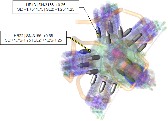
3D Feature Markers
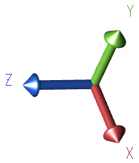
Axis Triad
Views have an axis triad that represents the coordinate planes of a 3D image within the view. The Axis will follow the orientation of the image as it is rotated. The properties of the axis triad can be modified in the View annotation properties.
Leader Lines to Data
Leader lines are the lines that are attached from the source annotation to another location you determine. See the topic Leader Lines for more information.
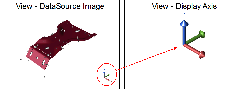
Auto Orient Views
The View in a report with a 3D DataSource image can be set up to automatically adjust how the 3D model is rotated and/or zoomed to best display the data currently loaded. See the topic Auto Orient a View for more details.
Cutting Planes
Cutting planes are used to hide geometry on one side of a plane. One or more cutting planes can be added to the model to create a View that shows only part of the model. See the topic Cutting Planes in CM4D for more details.
Transparency
The opacity of the model can either be read from the CAD file or set on the View. Changing the transparency of the model allows you to see through a complex scene to view or select the Feature markers. See the topic Annot Properties - View Tab for View settings.
![]()
Can we improve this topic?