Leader Lines
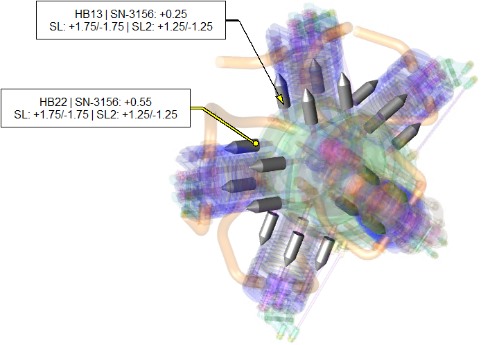
Leader lines are the lines that are attached from the source annotation to another location you determine. Leaders can be set to a specific point on the sheet or attached dynamically to a specific data point on a 3D model.
Leader Line Properties
The size and appearance of the lines can be modified via the Leader tab of the Annotation Properties. See the topic Annot Properties - Leader Tab for details.
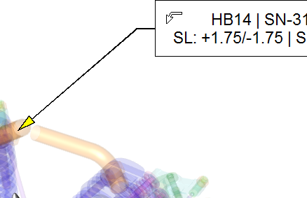
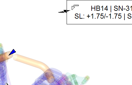
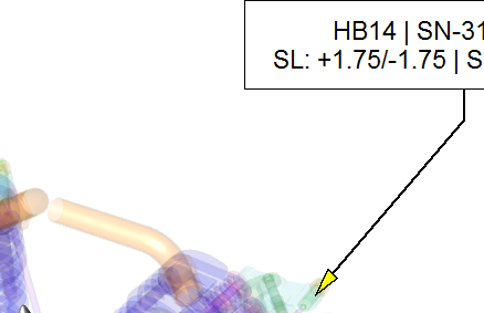
Terminator
The terminator is the style of the end point of the line. This can be none or set to a specific shape. See the topic Annot Properties - Terminator Tab for details.
Modify Leader Lines
The leader lines can be modified two ways using the Edit Leader tool by either setting the leader to a point on the sheet or adding a bend to the line.
Set Leader Location
You can move the leader line to point to a specific point on the sheet. This allows you to use a visual manual method to populate the annotation properties Leader Type Locate at A/B values.
To set the leader location:
Select the Edit Leader ![]() tool.
tool.
Click inside the annotation hold the mouse button down.
Drag the leader to a point on the sheet.
Release the mouse when the leader is pointing to the desired location.
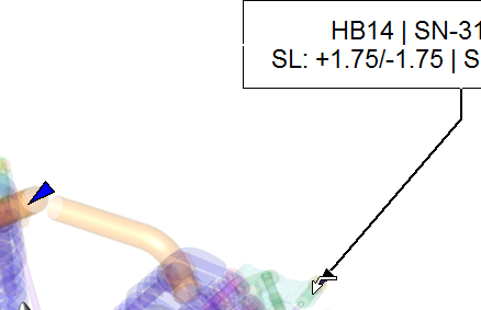
Alter Leader Line
You may want to alter the leader line to avoid an object or to change its appearance. This can be done by adding kinks that add a bend to the straight line.
To create kinks in the leader line:
Select the Edit Leader ![]() tool.
tool.
Hold the Shift key.
Click inside the terminator of the leader and hold the mouse button.
Drag the edit leader tool.
Can we improve this topic?