) button from the Toolbar.
Topic Contents: Hide
Whether you are using 3D Images or 2D Images in your View, leader lines may be added and saved to the database if they are not added when the data is processed into the database.
1. To add an image to your Routine, you can either put it into the Inbox, drag and drop it into the Reporter interface, or add it manually using DataUtility.
2. Once the image is associated to the Routine, Load the Routine in CM4D Reporter.
3. Select the Edit Leader w/ Tool () button from the Toolbar.
4. Click on the feature annotation that you want the leader to start from, hold the left mouse button and drag it over the image to the location you want to connect it to, then click the right mouse button to assign the location.
5. Exit the view (click outside the blue border).
6. Save your changes to the database by right-clicking on the main Routines node and selecting Save to Database.
7. Repeat steps 3 through 6 for any other feature annotation that you want to assign leader lines for.
3D Images typically have the necessary Nominal information in the data file for leader lines to be connected automatically. However, if your data files do not contain that information, then you can add leader lines manually as outlined above. The same rules will apply to manually applied leader lines for 3D images as for 2D images, however.
You can also assign 3D leader locations to an alternate location using the Coord X3, Y3, and Z3 feature types. The Coord XYZ 3 associations are used solely to assign 3D leader locations to a location other than that of the standard Nominal XYZ point. If no XYZ3 values are found, CM4D will then look for any Coord X2 or Y2 values. If neither of these exist, then the standard nominal points will be used for the leader lines.
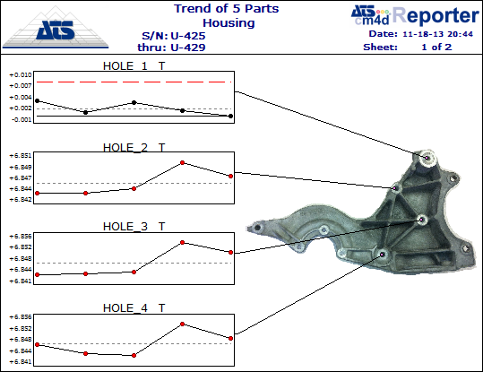
| Default 3DView w/ Leader Lines | 3D View w/ Leader Lines - Zoomed in and Rotated |
 |
 |
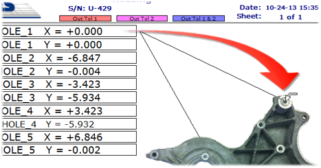
If leaders are assigned to a 3D image using the Edit Leader w/ Tool, the leaders will be disconnected from the XYZ nominal positions and will become statically located in position relative to the sheet. In other words, the leader will no longer move when the 3D image is rotated or zoomed.
To re-attach the leader to the XYZ nominal position on the 3D view, use the Edit Leader w/ Tool and drag the leader back onto the annotation.
After dropping the leader, the page will refresh and the leader will now be attached to the 3D image.
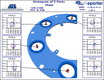
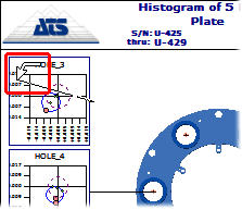
2D Images cannot be rotated or zoomed within the view, and leader lines cannot be connected to the feature points using Nominal information from the data. You can create static leader lines with terminator point locations that will be saved to the database. However, if the 2D Image changes or is moved within the view, you will need to reassign all of your leader lines, since they are saved to a specific location in space relative to the View area.
The Coord X2 and Coord Y2 associations are used solely to assign 2D leader locations to a location other than that of the standard nominal XYZ point. 2D leaders assigned using these associations will be located within the view. The position within the view is based on the value assigned to the characteristic. Values are between 0 and 1 (using decimals as percentages), zero being the left/bottom of the View and one being the right/top of the view.
These nominal values can be created by the DataSmith translator by assigning Coord X2 and Coord Y2 feature associations. However, if no X2Y2 values are found when data is loaded from the database, then the leader lines must be created manually using the Edit Leader w/ Tool.
To add a leader line to a 2D image:
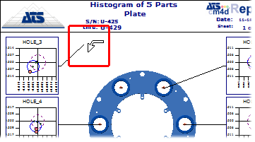
1. Select the Edit Leader () tool.
2. Click and hold the mouse on the annotation to which you want the leader line to begin.
3. Drag the line on to the image.
4. Drop the line in the location that you want the line to terminate.
5. Click and hold the left mouse button on the feature annotation that you want the leader to start from.
6. Drag it over the image to the location you want to connect it to, then release the left mouse button.
7. Save your changes to the database by right-clicking on the main Routines node and selecting Save to Database.
8. Repeat steps 2 through 6 for any other annotation that you want to assign leader lines for.
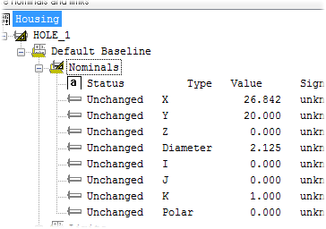
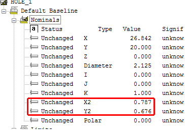
9. To check the X2 Y2 values added, right click on the annot and select Edit Feature.
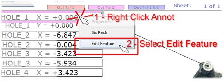
10. In the Feature Editor, check the value of the Nominals for the Type X2 and Y2.
|
Feature before Adding Leader Lines |
|
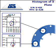
Feature After Adding Leader Lines |
|
|
|
|