In this Topic Hide
A component is an inspectable part where an inspector can enter a defect. It is comprised of a part and location combined. For example, a part is a headlight and a location is left side. Together, the headlight + left side is a component.
Components can be created when adding them to the view as shown below. Alternatively, they can be created in the Part/Locations window (see here).
1. Select the layer you want to add the component to.
2. Select the Design tab in the ribbon.
3. Click Add Component. Alternatively, you can right click on the layer in the View Explorer and select Add Component from the context menu that appears.
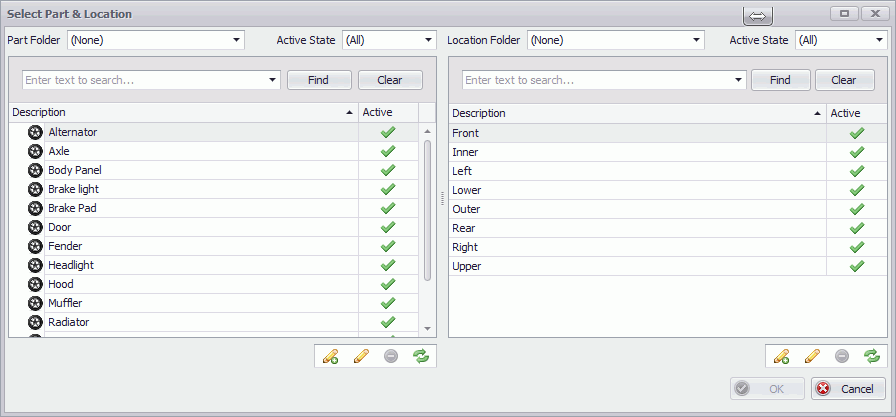
The part and location selection window opens.
4. If required, use the folders or search options to filter the lists.
5. Select a part with or without a location in one of the following ways:
o If you want to add a part without a location, select the part in the left-hand pane.
o If you want to add a part with a location, expand the part by click on the arrow next to it, select one of the locations associated to it.
o If you want to add a location to a part, drag and drop the location from the right-hand pane onto the part in the left-hand pane, select the location in the part.
You can create a new part or location by clicking the Add
button ( ) beneath their respective
panes.
) beneath their respective
panes.
6. Click OK.
The component definition window opens.
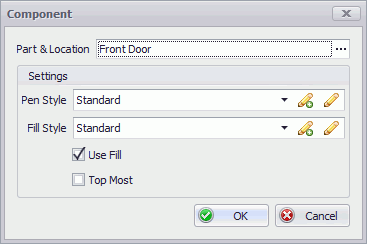
7. If the part/location is
incorrect click  to change it.
8. Select, add or edit a Pen Style. This will be the outline of the component.
9. Select, add or edit a Fill Style. This is the color of the component that will overlay the image.
10. If you want to define a transparent component, deselect the Use Fill checkbox. The component will only be outlined on the view. There won't be a fill color or pattern applied to the component.
11. Select the Top most checkbox if the component may be covered by another component but you still want to be able to place a defect on it.
Once a component has been defined on a view, it is not possible to check or uncheck the Topmost checkbox. Plan your setup carefully!
12. Click OK.
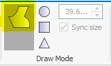
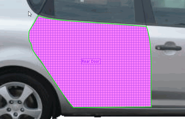
The cursor changes to a pencil icon, indicating you are now ready to outline the component on the view. This can be done by drawing it using lines and curves or by adding pre-defined shapes.
The following steps are carried out when adding a component shape. The default setting will allow you to draw a shape using lines and curves. You can select this setting while editing a shape by selecting the following button in the ribbon menu.
1. Click on the view where you want the edge of the component to begin.
You now have the option to draw a line or a curve. By default it will draw a line.
You can switch to drawing a curve by pressing the Tab key or the C key. Switch back to drawing a line by pressing the Tab key again or the L key.
2. Click at the next point along the edge of the component.
3. If you selected to draw a curve you can now create the curve by moving the curve handles.
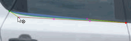
4. Keep drawing around the edge of the component.
5. When are get close to the starting point again, press the F2 key or double-click on the starting point.
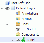
The component is created and listed in the View Explorer.
If you want to give a name to the shape then select it in the View Explorer and add a description in the Properties pane.
The following steps are carried out when adding a component shape. You can define the outline of a shape as a circle, square or triangle using the preset shapes.
1. Select the required shape in the ribbon menu.
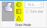
You must make the shape the right size before you place it. This is done as follows:
o Ctrl key + Mouse wheel: Change radius by 10 units
o Ctrl key + Shift key + Mouse wheel: Change radius by 1 unit
2. Adjust the size of the shape as required.
3. Move the shape into position and left-click to place it.
The shape is placed on the view.
1. Select the component shape in the view or in the View Explorer.
If Select Single Shape is enabled in the ribbon then you will select the component shape. If it is disabled you will just select the component.
2. Select the Design tab in the ribbon.
3. Click Edit.
4. Make changes as described below.
5. When completed press the Return key to save the changes. Press the Cancel key to cancel the changes.
Move the mouse over the middle of the shape and then left-click and drag it into position.
Move the mouse over the vertex so that it is highlighted and then click and drag it into position.
Move the mouse over the line so that it is highlighted and then click and drag it into position.
Move the mouse over the line so that it is highlighted and press the S key. A new vertex will appear in the middle of the line.
Move the mouse over the line so that it is highlighted and press the C key to turn a line into a curve or the L key to turn a curve into a line.
1. Select the component that already has a shape in the View Explorer.
2. Select the Design tab in the ribbon.
3. Click Add Shape.
4. Draw the shape as described previously.
5. When completed press the Return key to save the changes. Press the Cancel key to cancel the changes.
The component is now made up of multiple shapes.
Sub-components allow a manufacturer to zero in on possible specific high risk sections of a component. Sub-components are actually invisible to the inspector as they will just see the whole component.
Sub-components are created by combining a location with a sub-part (or by simply placing a sub-part on the view). Sub-parts are simply divisions of a part. For example, the door on a passenger vehicle could be divided into upper door and lower door or some other combination.
1. Select a component in the View Explorer.
2. Select New > Sub-component.
3. Click the Change button for the Sub-part field.
You can create sub-parts at this point by clicking the Add button or else you can create them all beforehand in Cockpit (see here).
4. Select the desired sub-part from the list.
5. Click OK.
6. Click OK on the Sub-Component Properties dialog.
7. Outline the sub-component area.
8. Press F2 when finished.
9. Click Yes to confirm that you want to save this sub-component.
You will often need to draw holes within a component. This can be done using a Subshape.
1. Select the component shape in the view or in the View Explorer.
If Select Single Shape is enabled in the ribbon then you will select the component shape. If it is disabled you will just select the component.
2. Select the Design tab in the ribbon.
3. Click Add Subshape.
4. Draw the subshape within the existing shape.
5. When completed press the Return key to save the changes. Press the Cancel key to cancel the changes.
The component now has a hole in it.
1. In the View Explorer select the component.
2. In the Properties pane click the down-arrow next to the Fill Style or Pen Style.
3. Select a style from the list.
For information on adding and modifying fill and pen styles, see here.