To access the properties for Feature Markers, right-click on View Annotation and select Properties. Go to the View tab and click Feature Markers.
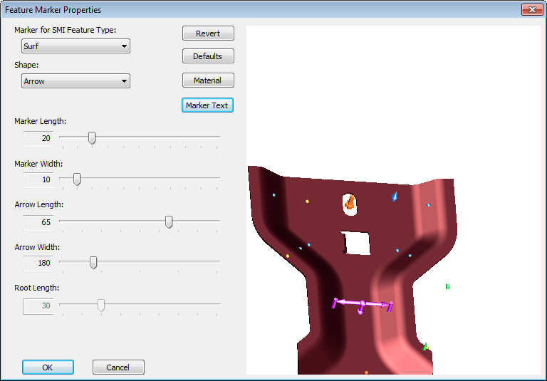
Feature Markers are used to display the feature point within a view. Each SMI Feature Type can be assigned its own marker type. There are various Shape and size values as well as a full range of Material options available within the Feature Marker Properties dialog. All of the feature markers are shown in a fixed place on the example model in the dialog. The part will be moved and zoomed according to the Feature Type selected, but you can also move it around with your mouse.
 Reference
The
example image in the Feature Marker properties dialog is built in, and
cannot be altered to show your document or routine image.
When manipulating the example view provided in the right-hand side of the Feature Marker Properties dialog, the following hot keys may be used in conjunction with the mouse:
· Translate (Pan) - Hold down the Shift or Ctrl key (or the hold the mouse wheel) and drag the image as desired.
· Spin - Hold down the left mouse button, drag the image in the desired direction, and then release the mouse button. Image will continue to spin on its own. To stop spin, click image again. To speed up or slow down the spin of an image, increase or decrease the speed at which you initially pull the image and release the left mouse button.
· Rotate - Hold down the left mouse button and drag the image in the desired direction.
· Zoom - Hold down Shift + Ctrl, click the left mouse button in the preview pane, and drag the image as desired. Another option for zooming may be utilized if your mouse has the wheel feature. Moving the mouse wheel forwards or backwards while positioning the cursor over the preview pane will zoom the image in or out.
There are several markers available for each available feature type. After selecting which Marker for SMI Feature Type and the marker Shape, you can select a different material.
To select the feature type you want to modify, click the Marker for SMI Feature Type dropdown menu and choose from the list of SMI Types. The Feature Marker displayed in the right pane will zoom and position to preview the example feature type marker selected. The SMI feature types available are: Surf, Hole, Slot, Mid, Ref, Flush, Gap, Non, XYZ, and Plane
Select one of the available 3D image options: Sphere, Cube, Cone, Tube, Arrow, Squared Cross, or Rounded Cross.
The Shape of the Feature Marker cannot be changed for Midpoint, Range, Distance, and Plane constructed feature types.
Revert will return the feature marker you are currently altering to its last saved state, both color and size.
Defaults will return all of your feature markers back to the system defaults. The defaults related to this button are built in specifically to defaults existing for v11.3 and higher markers, and will affect any feature marker "defaults" that have been migrated from an older version.
 Example
If
you migrate feature markers from a v10 up to v11, you may have the default
"red tomato" (red sphere) markers for all feature types. If
you then click the Default button, these red spheres will be changed to
the upgraded default marker settings, both size and material.
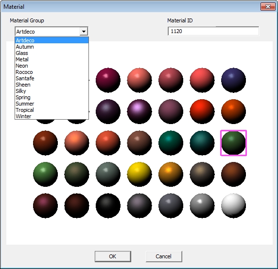
The Material, or appearance, of a feature marker may be customized using the Material dialog. Select a Material Group from the drop down list, and then click one of the example spheres to assign the selected material to the feature marker. A pink square will appear around the currently selected material sphere. Click Ok to save your Material selection.
· Material Group - Materials are arranged in groupings of coordinating shades and textures.
· Material ID - Each material selection has a unique ID number. The ID number allows you to set a specific material quickly and precisely without searching through the material groups and selecting a material by visual inspection alone. This ID is also used to assign Materials via DataUtility.
Marker Text can display information about existing feature markers that identifies the feature on a 3D model within a view. The Marker Text will only be displayed while the view is in Edit Mode. While in Edit Mode, the marker text will remain on or near the feature as the model is rotated or zoomed.
The text can be configured with CM4D variables to resolve the following feature values:
· Label
· Description
· Alias
· Sequence
To set the Marker Text:
1. Open the View Annot Properties dialog.
2. Click Feature Marker.
a. In the Feature Marker Properties dialog, click Marker Text.
b. Select the Enable Feature Marker Text check box.
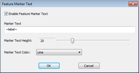
c. In the Marker Text field, enter a feature variable (e.g., ~label~ or ~alias~).
d. Set the Text Height by dragging the slider left or right.
e. Select a Text Color from the dropdown.
 Notice
Sample
variables will not resolve when used as Marker Text.
f. Click OK to apply.
3. Put the view into Edit Mode to view the feature Marker text.
To disable the Marker Text, uncheck the Enable Feature Marker check box in the Feature Marker Text dialog.
There are several marker size settings available for each feature marker. After selecting which Marker for SMI Feature Type and the marker Shape, set the remaining options.
· Marker Length - Marker Length indicates the overall length of a marker.
· Marker Width - Marker Width indicates the overall width of a marker. In the case of the Sphere and the Cube, this setting applies the entire aspect size of the marker.
· Arrow Length - Arrow Length refers to the length of the head of the arrow marker. This length is a percentage relative to the overall marker length.
· Arrow Width - Arrow Width applies to the width of the head of the arrow marker. This width is a percentage relative to the overall marker width.
· Root Length - Root Length applies to the Squared Cross and Rounded Cross marker shapes. The "Root" of these marker shapes refer the "cross" section located directly on the feature point. This allows you to see exactly where the feature originates, so that you can see if the marker is on the surface or somewhere inside the image. The root length is a percentage relative to the overall marker length.
The size of feature markers are relative to the size of the image, so the size values represent a percentage rather than an absolute size. The sliders operate exponentially; the length of the marker increases at a faster rate the longer it gets. If you are setting the Marker Length to a shorter length, the increments will be very small, whereas if you are setting the marker to the longer settings, the increments will be much larger. Some sliders may not be enabled depending on which shape you choose. If you choose the Sphere, for example, only the Width slider is available, as none of the other size options would apply to a sphere.
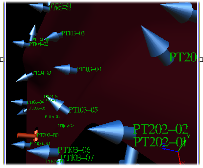
If vector information is available, Markers for Features will indicate the I, J, and K values of a feature, as shown in the image below.