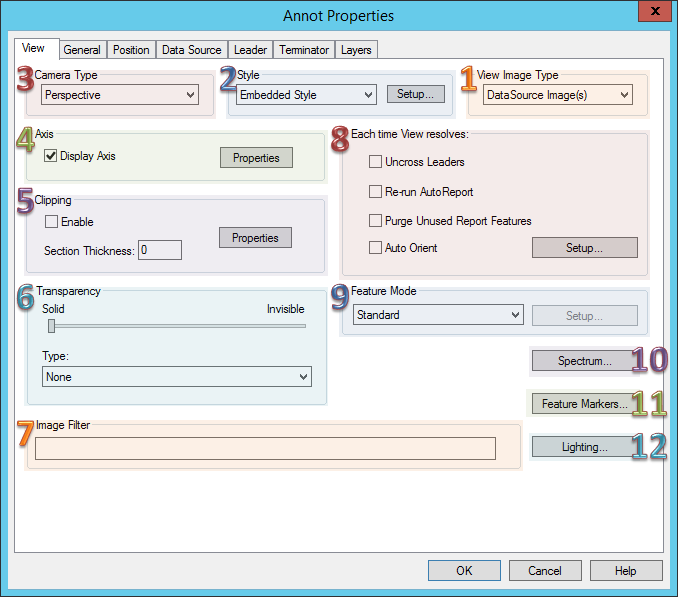
The View tab of the Annot Properties dialog allows you to modify the various properties of a View annotation.
There are four View Image Type options:
· No Image - Displays only feature markers in the view.
· DataSource Image(s) - Displays an image that is saved in the database and associated to the View's DataSource. See the topic Images in CM4D.
· Document Image(s) - Displays an image that is saved in the document. See the topic Document Images.
· Display View Axis - Displays only the View axis. See the topic View Axes.
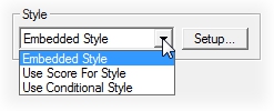
Within Style, you can choose a Style type to apply to the View. Style options include: Embedded Style (default), Use Score for Style, and Use Conditional Style.
There are two Camera Types which can be used for a View annotation in CM4D:
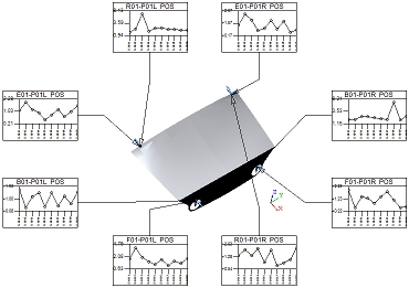
· Orthographic
- An Orthographic view is on having perpendicular lines and no converging
points. This type of view may be used for technical purposes, such as
use with displaying Alignment
reports. Orthographic views are reminiscent of the visualization used
with v10 CM4D Views.If a document is using old Visualization, the views
will have Orthographic camera types by default.
Click to see an
Orthographic View >
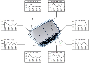
· Perspective
- Views with a Perspective camera type are those which will display 3D
images and depth relationships on the two-dimensional surface of a View.
In other words, images will appear to have vanishing points and depth
within a View, representing a "natural" view of a 3D image.
Perspective is the default camera type for all views.
Click to see a Perspective
View >
See the topic View Axes.
The Clipping section of the View Properties dialog allows you to enable or disable clipping, define a section thickness, and define the plane which will be sectioned.
See the topic Clip a View for more information.
See the topic View Transparency.
See the topic Image Layers.
Select any of the following options you want to apply each time a View is resolved.
When the Uncross Leaders check box is enabled, any leader lines attached to your view will be automatically uncrossed each time the View is resolved. The Uncross Leaders function will only work properly if the View is connected to the same DataSource as the Annot with which it is connect
The Re-run AutoReport check box enables the continuous Auto Report function. This option allows the Auto Report to be run on an individual View, so that each time the View is resolved, the existing Auto Report is refreshed. If this check box is enabled, and Undo AutoReport Layout is selected from the Sheets Menu, the following warning dialog will appear:
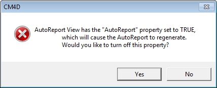
Clicking Yes in the warning dialog will disable the Re-run AutoReport check box in the View Properties and remove Auto Report from the View. The Re-run AutoReport function differs from the Sheet Auto Report in that at the Sheet level, Auto Report must be Run from the Auto Report dialog each time DataSet information is modified. Using the View Properties Re-run AutoReport allows the Report to automatically resolve any changes made to the DataSet information in the Report each time the view is resolved.
The Purge Unused Report Features check box determines whether or not feature markers will be displayed in the View. Any features included in the View that do not have associated annot on the sheet will not have feature markers displayed in the View when the Purge option is enabled.
 Tip
Tip
The
Purge option is particularly useful when running AutoReport
or ReportTweak, since
only the features relating to the particular annot on a sheet will be
shown in a View.
You can set up a View to orient the 3D image according to specific rules. To use the Auto-Orient functions, enable the check box and click Setup to configure the orientation options.
For more information, see the topic Auto Orient a View.
See the topic View Feature Mode.
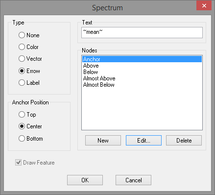
To change the properties of spectrum nodes, right click on a View and go to the Properties dialog. In the Annot Properties dialog box, click on the Spectrum button. Select an available Node. Click Edit to modify its properties, or click New to create a new spectrum node.
See the topic View Feature Markers.
See the topic View Lighting.