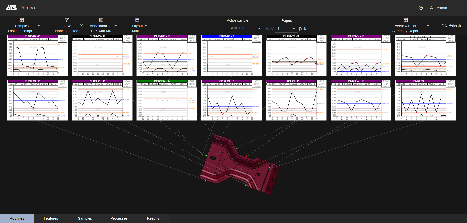
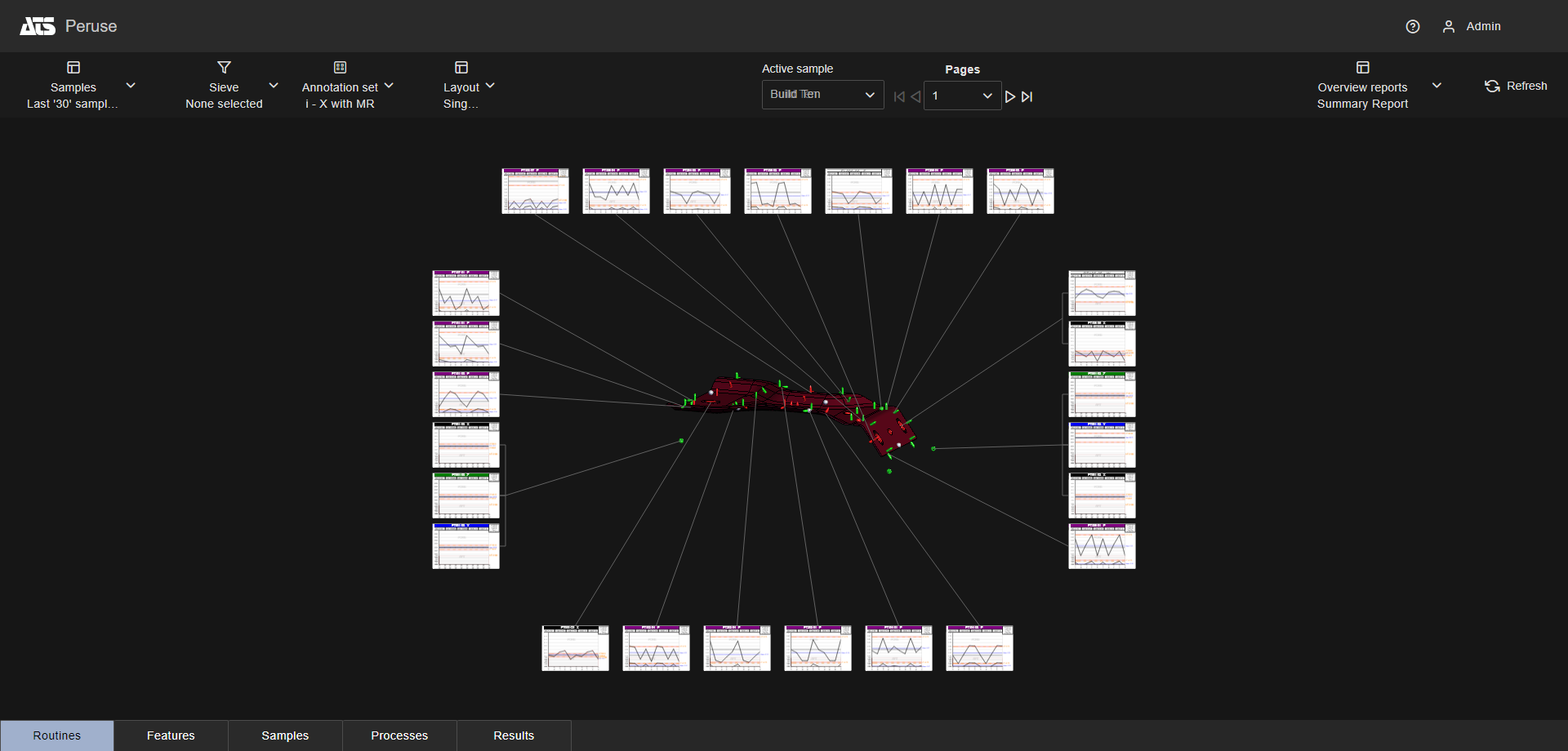
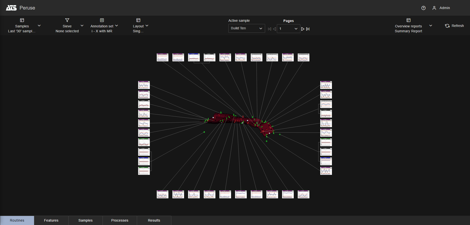
Multiple Page - Top 7x2
Layouts are predefined configurations of annotations (charts/graphs) connected by leader lines to feature markers on a 3D model in a central viewer area. Changes to data selection or model adjustment result in immediate updates to the layout contents, including redrawing of leader lines and annotation ordering. The type/style of the annotations in the layout is determined by the selected Annotation Set.
Layouts in CM4D Peruse are comparable to Auto Reports in CM4D Classic and Reports in CM4D Interactive, but with some functional differences.
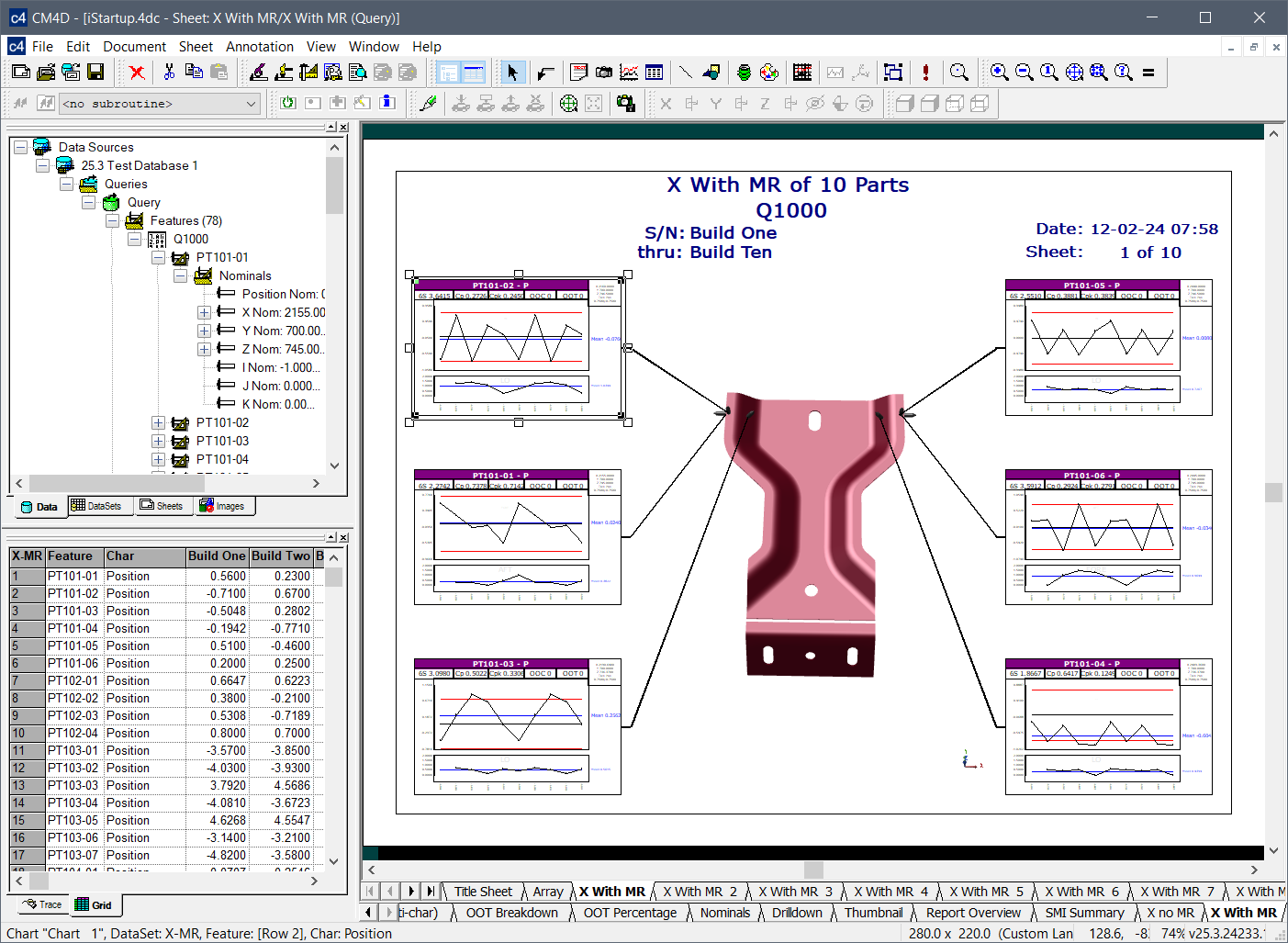
Auto Reports in CM4D Classic
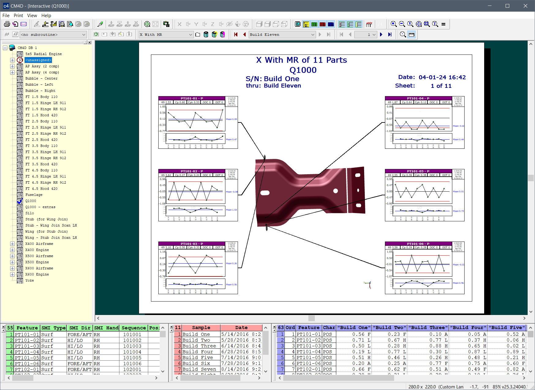
Reports in CM4D Interactive
Layouts in CM4D Peruse
Layouts can vary in number of annotations, where the annotations are drawn and how the annotation are arranged from page to page. Layouts only determine the placement or sizing of annotations. The annotation type or style is determined by what is currently selected in the Annotation Set dropdown menu. Other behavior options can be configured that determine how the annotations are organized within the screen area or how the layout effects the 3D model. A built-in option called 'Fullscreen' is available without any Admin Configuration, which shows only the 3D Viewer without any annotations.
See also:
Layout Configurations in CM4D Peruse
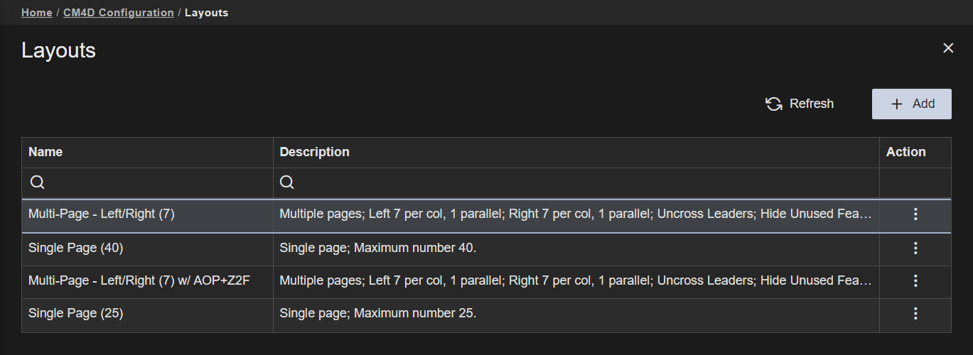
Layouts are configured by defining the placement and number of annotations on each side of the 3D viewer, along with some options related to orienting the 3D model to best display feature markers for the loaded annotations.
 |
|
| Action | Click the three dots
to open the menu of available actions for the selected row.
|
| Description | An optional description field for the Layout. This could be used to give a brief summary of the properties selected. The description is only used in this grid. |
| Name | The label of the Layout. This label appears in the Layouts dropdown menu in CM4D Peruse, so it should be identifiable to end users. |
|
New Layouts can be created by clicking the Add button in the top right of the Layouts card. The Layout Properties blade is opened. |
|
|
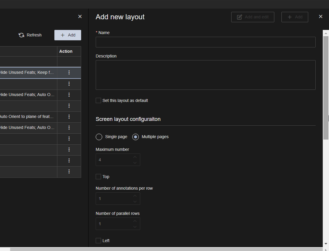 |
The Layout Properties blade contains the options for defining the Layout. To close the properties without saving, close the property blade.
    |
|
| Name | The label of the Layout. This label appears in the Layouts dropdown menu in CM4D Peruse, so it should be identifiable to end users. |
| Description | An optional description field for the Layout. This could be used to give a brief summary of the properties selected. The description is only used in this grid. |
| Set this layout as default | Enable to make the layout load automatically when a user first loads data in CM4D Peruse. If none of your configured layouts are set as the default, then the system loads the built-in layout Fullscreen. |
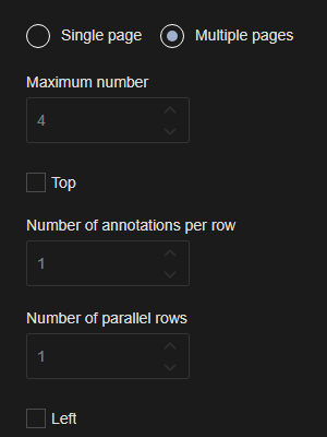
| Pages | The total number of pages is determined by the number of annotations required to load the current data. Annotations are automatically resized and distributed to fit the defined layout specifications of the page. Single page reports have one option to set the number of annotations to be shown on each page. Multiple pages are more flexible and allow you to choose the screen areas and the number of annotation per area. |
| Maximum Number | This option only applies to Single Page layouts. The highest number of annotations (up to 40) displayed on each page. Annotations exceeding this number are loaded as additional pages to include all loaded data. |
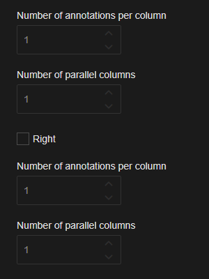
| Layout Screen Areas | The layout screen areas only apply to Multiple page layouts. Set the area of the page where annotation may be displayed around the 3D model. Set the maximum number of annotation per row (Top) or column (Left, Right) within the layout settings. |
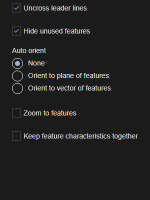
| Uncross Leader Lines | Leader lines attached to the 3D model are automatically uncrossed each time the 3D View is resolved. Annotations in the Layout are reorganized to accommodate the leaders in the optimal formation to prevent as many crossed lines as possible. This provides an unobstructed view of the 3D model and makes it easier to see which annotation relates to a feature marker. |
| Hide Unused Features | Any features for the 3D model that do not have corresponding annotation on the Layout page are hidden. This is useful for multiple page layouts because only the relevant feature markers are shown on each page. |
| Auto Orient | Automatically orients the 3D model to an optimal position based on the loaded features relative to the annotations in the Layout. The orientation can be done by Plane (XYZ) or by Vector (IJK). |
| Zoom to Features | Automatically adjusts the zoom of the 3D model so the currently displayed feature markers fill the 3D Viewer area. Each page of the layout provides a best-fit zoom to optimize the view area to highlight the features displayed in the annotations. |
| Keep Feature Characteristics Together | Characteristics belonging to one feature are displayed on a single page, preventing the separation of characteristics across different pages. There are some cases where splitting up characteristics between pages cannot be avoided. Layouts with this option disabled have no strict requirement to display all characteristics from one feature on a single page, although the data ordering may result in some characteristics appearing on the same page. |
This section provides further explanation and examples of the various layout properties as they appear in CM4D Peruse.
The total number of pages is determined by the number of annotations required to load the current data. Annotations are automatically resized and distributed to fit the defined layout specifications of the page. Single page reports have one option to set the number of annotations to be shown on each page. Multiple pages are more flexible and allow you to choose the screen areas and the number of annotation per area.
Annotations are automatically resized to show the Maximum Number of annotations on each page and are organized around the four sides of the 3D Viewer. Annotations exceeding the set maximum number are loaded on additional pages as needed to accommodate the remainder of the loaded data.
Single Page - Maximum Number: 9
Single Page - Maximum Number: 25
Single Page - Maximum Number: 40
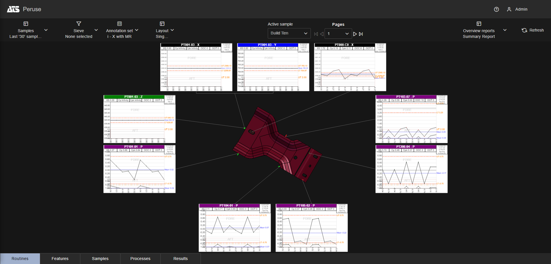
Annotation are automatically resized and distributed to show the specified number of annotation in one or more of the three available areas around the 3D Viewer (Top, Left, Right).
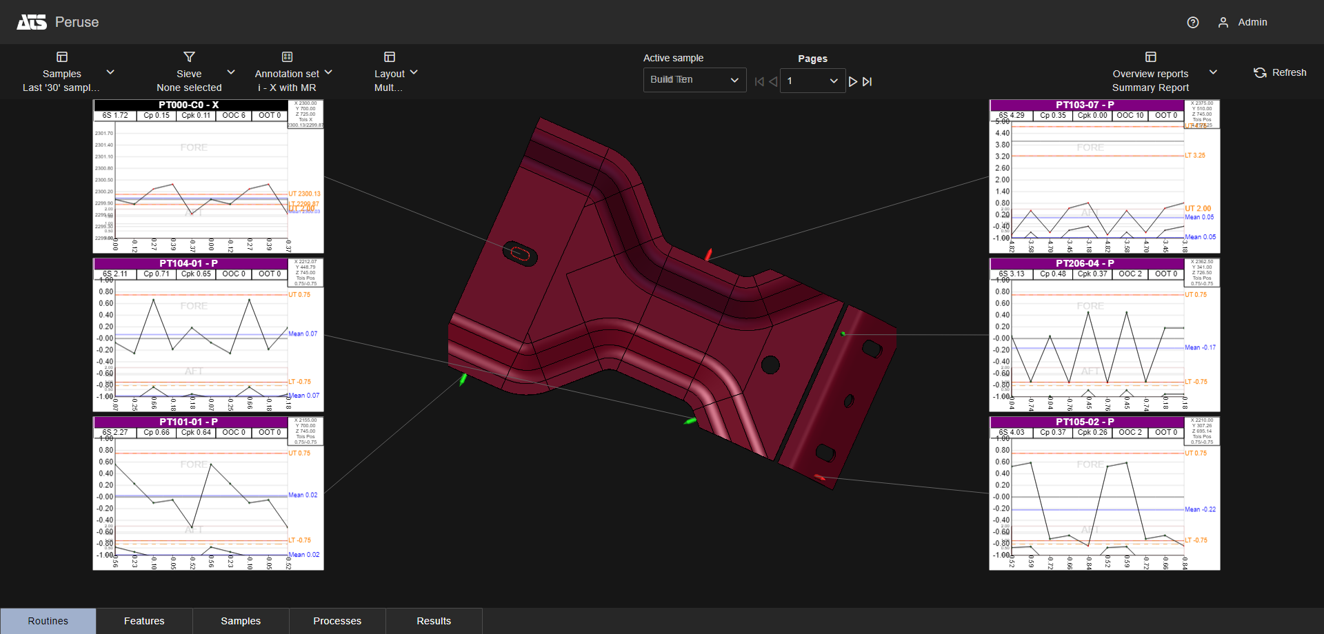
Multiple Page - Left 3x1, Right 3x1
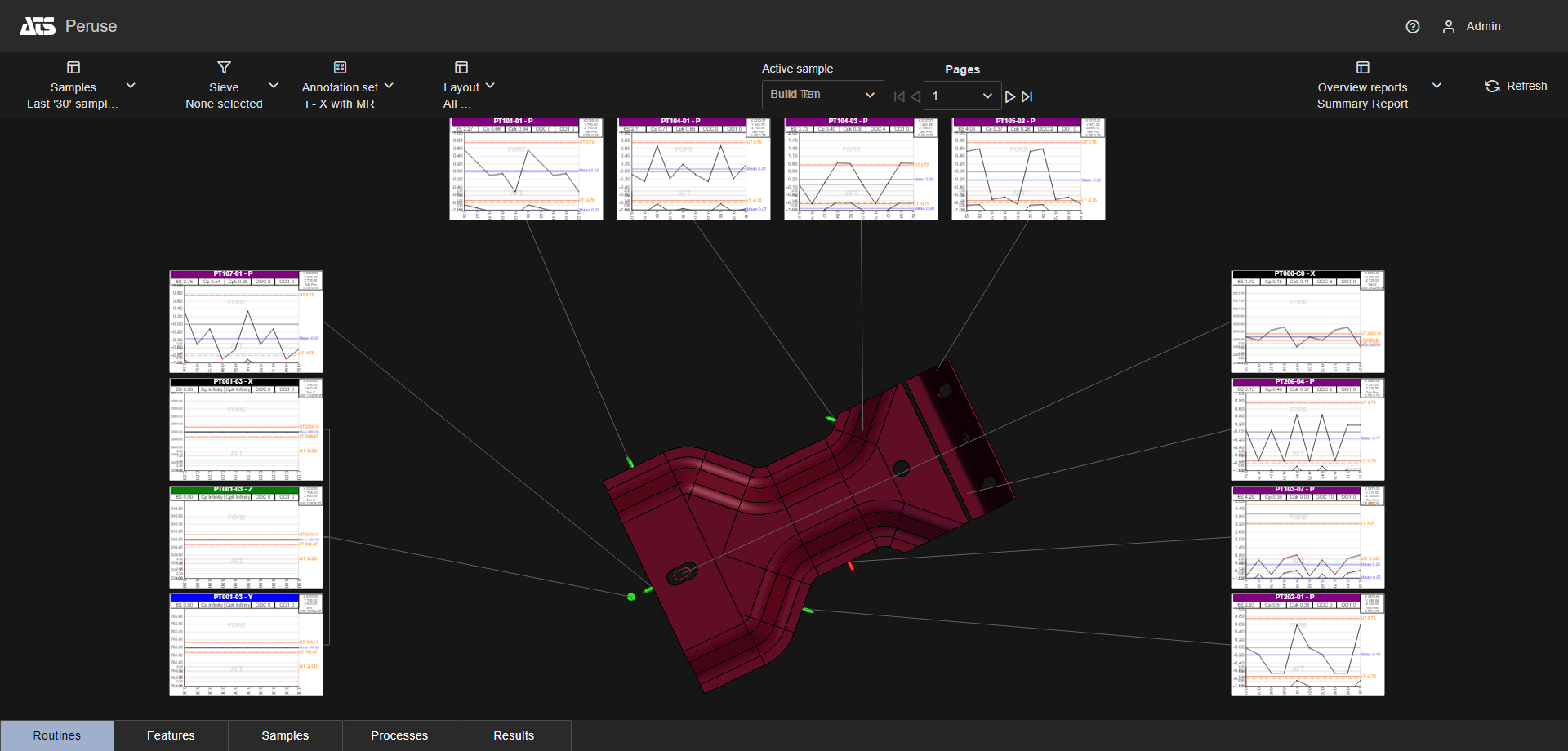
Multiple Page - Top 4x1, Left 4x1, Right 4x1
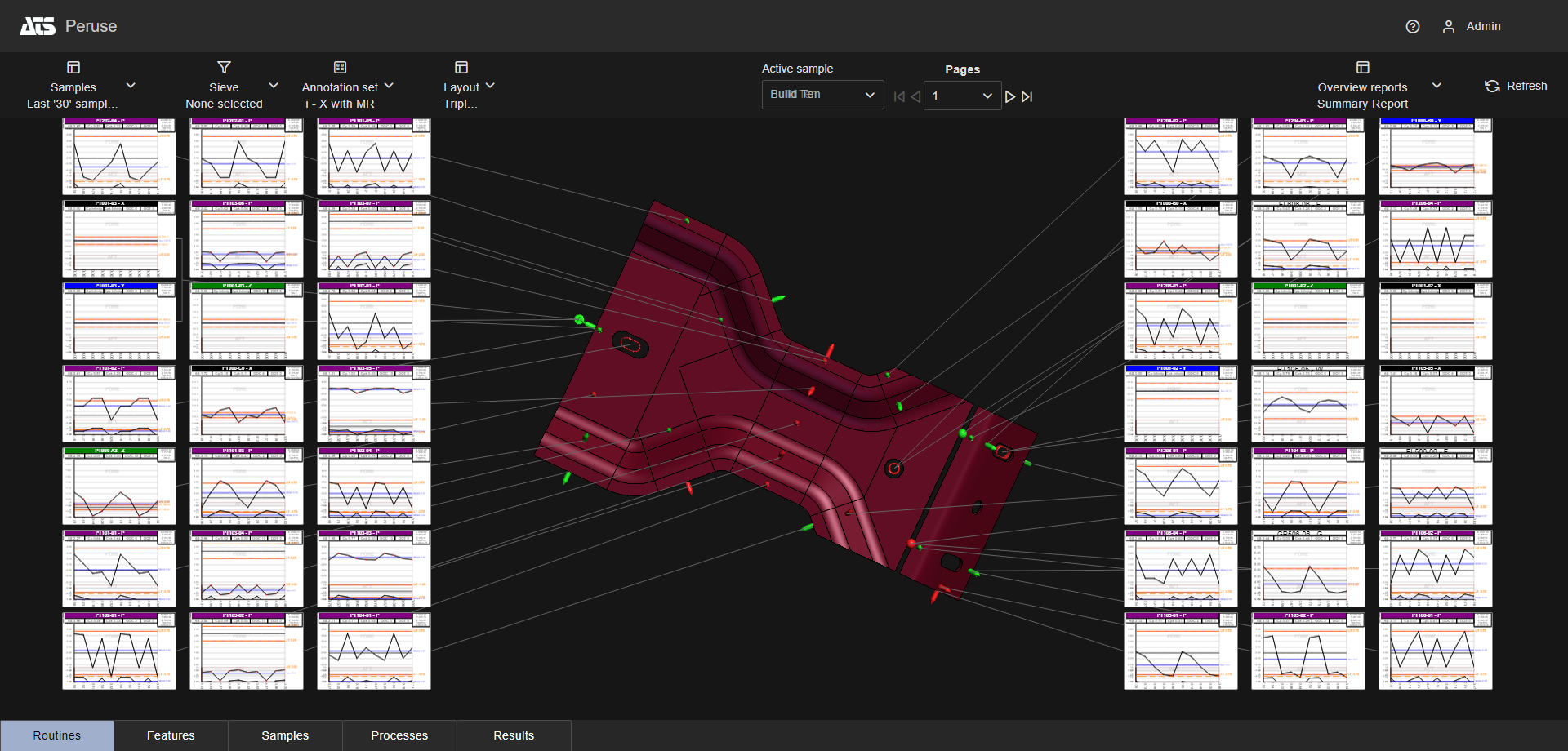
Multiple Page - Left 5x3, Right 5x3
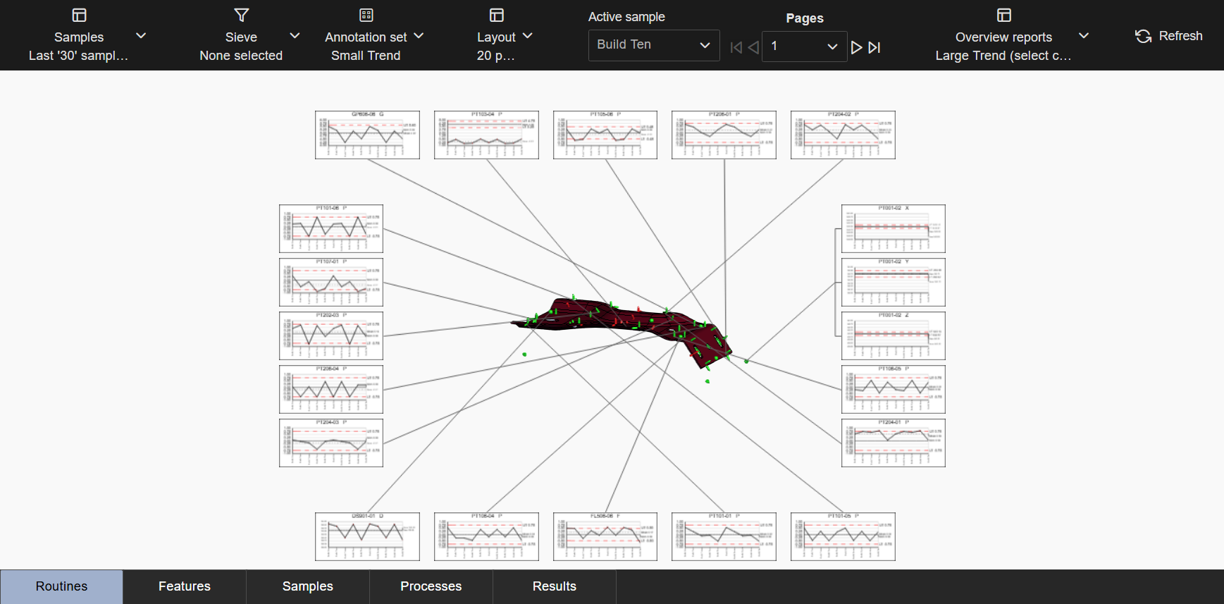
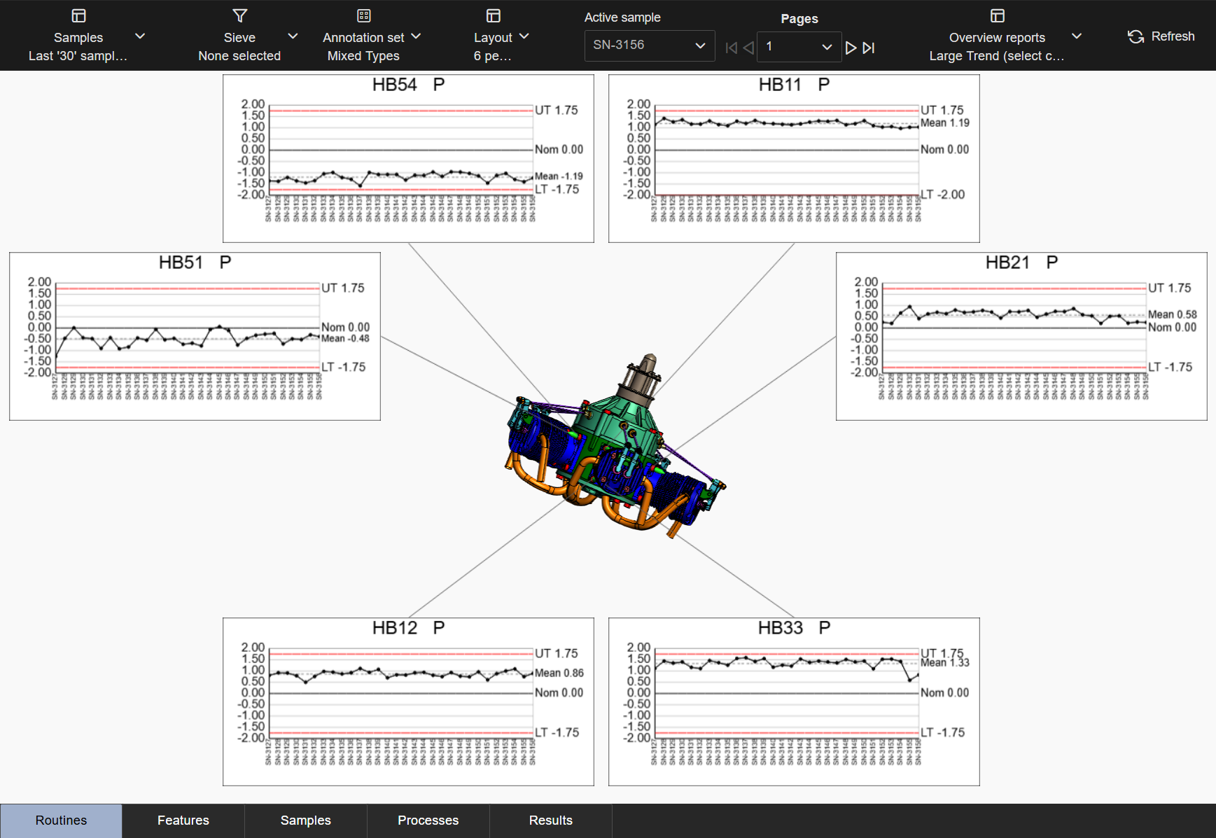
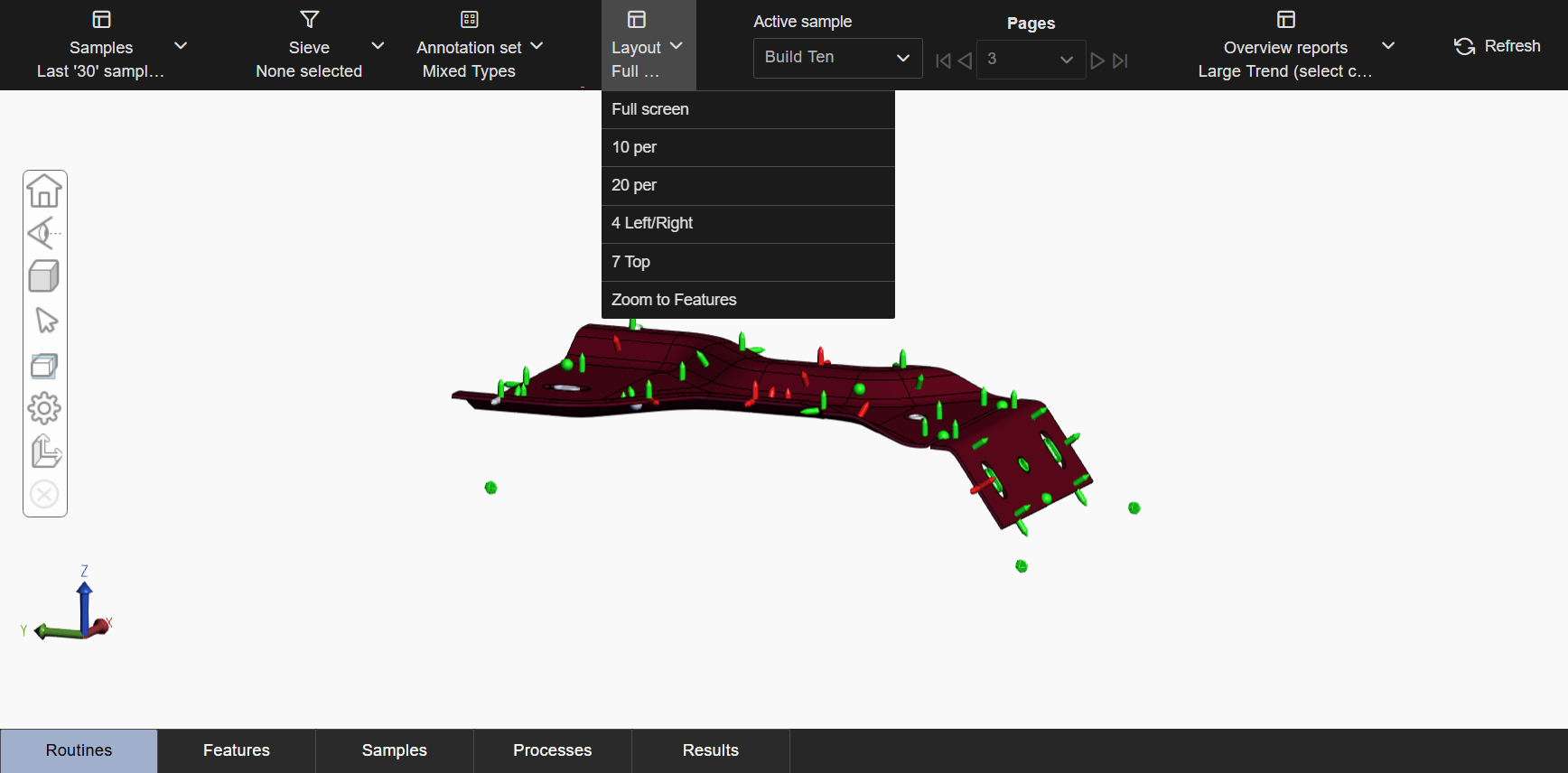
Multiple Page - Top 7x2
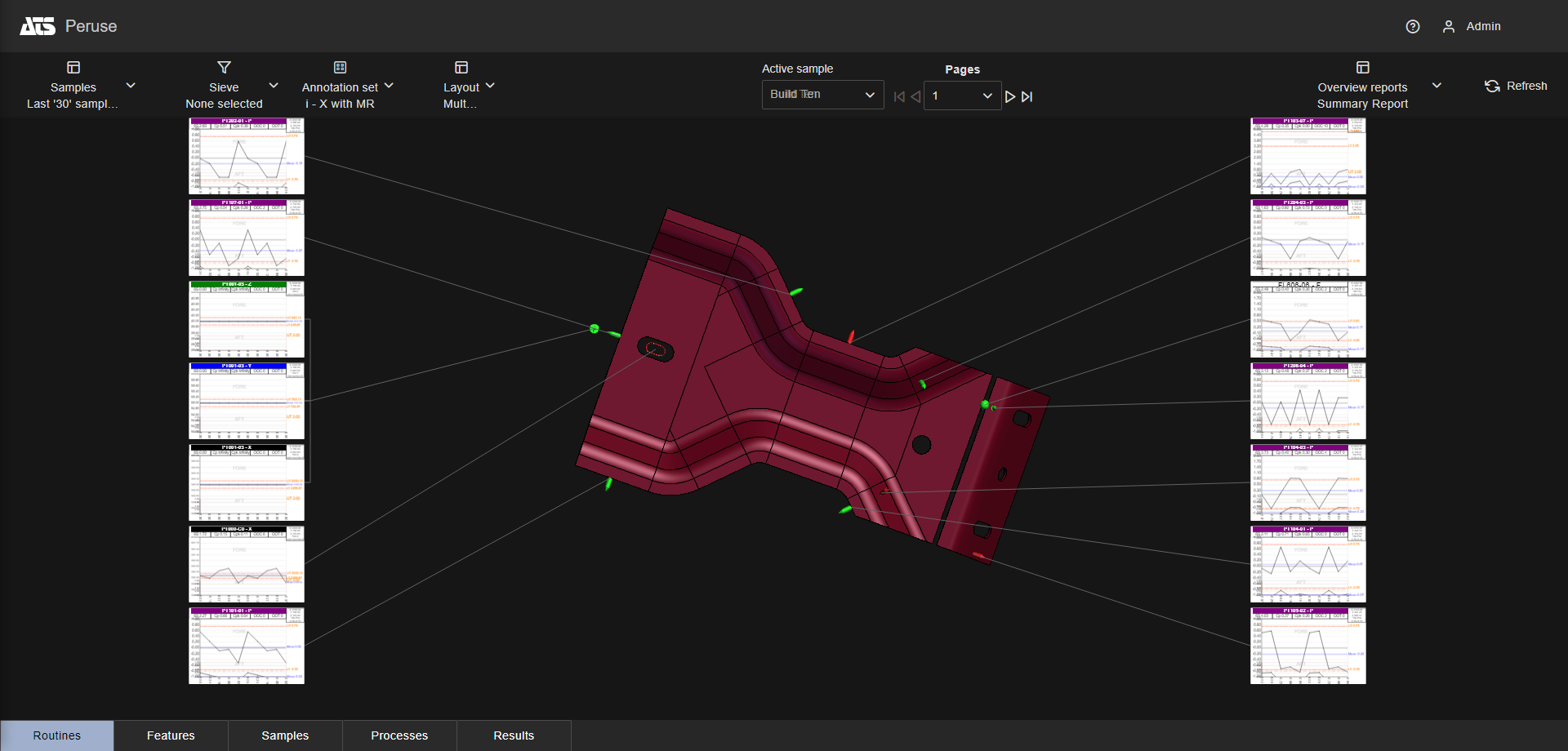
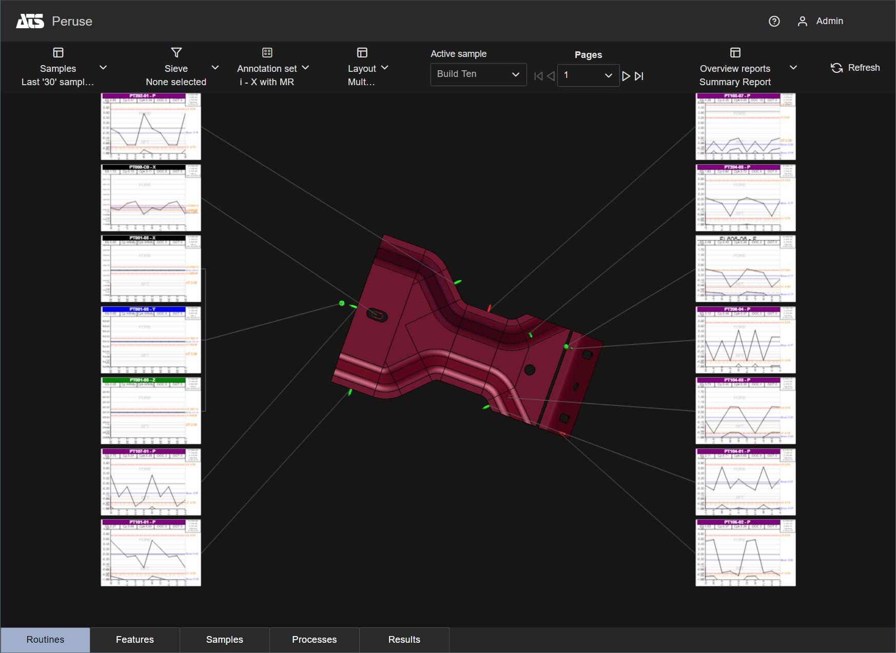
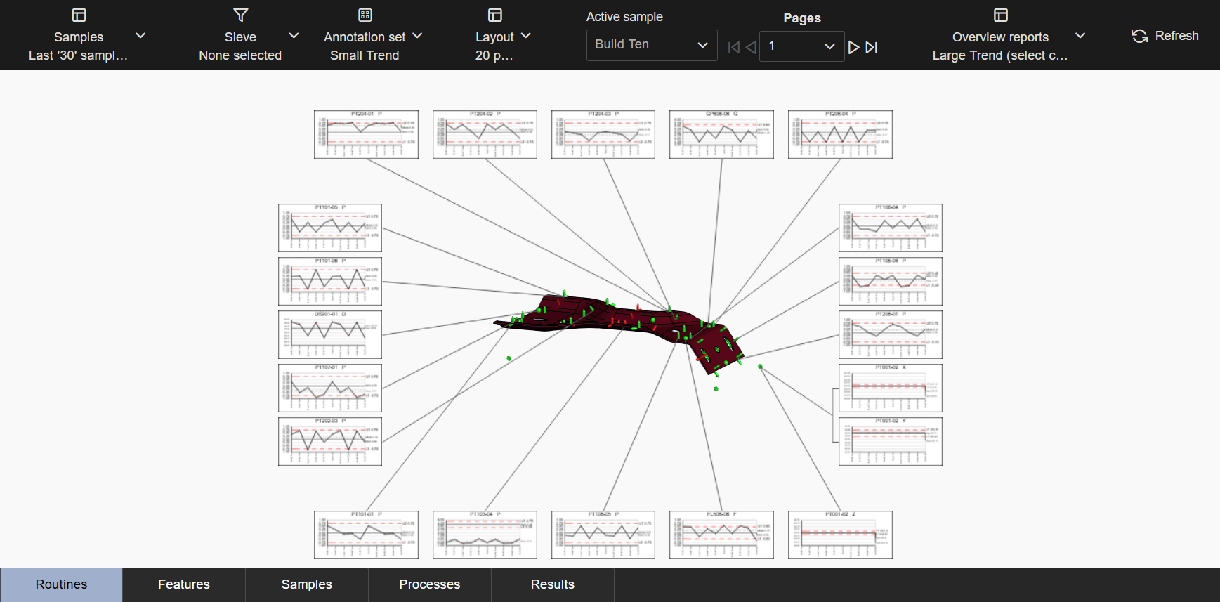
Multiple Page - Left 7x1, Right 7x1
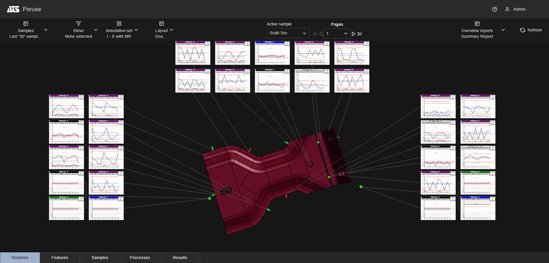
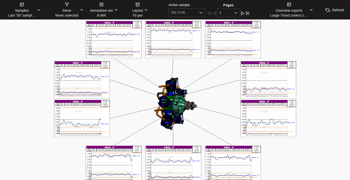
Multiple Page - Top 5x2, Left 5x2, Right 5x2
This option only applies to Single Page layouts. The highest number of annotations (up to 40) displayed on each page. Annotations exceeding this number are loaded as additional pages to include all loaded data.
For example, if a Single page layout is set to a maximum number of 30, and the data loaded requires 67 annotation, you would end up with two pages with 30 annotation each and one page with the remaining seven annotations.
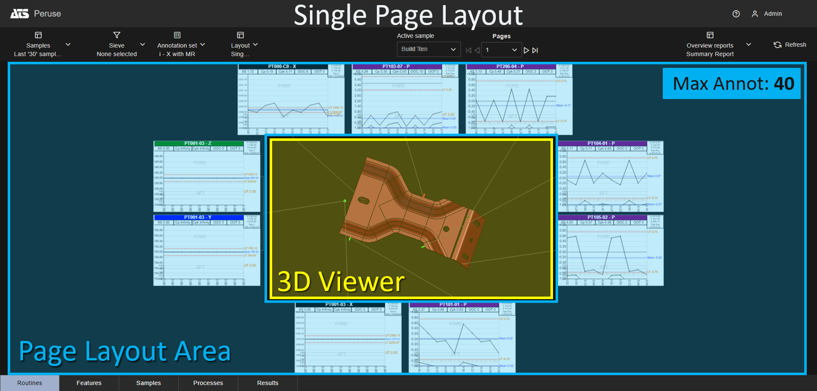
Single Page Layout areas
The layout screen areas only apply to Multiple page layouts. Set the area of the page where annotation may be displayed around the 3D model. Set the maximum number of annotation per row (Top) or column (Left, Right) within the layout settings.
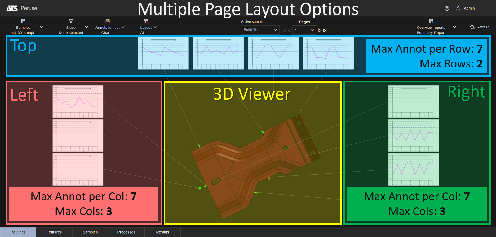
Multiple Page Layout areas
Leader lines attached to the 3D model are automatically uncrossed each time the 3D View is resolved. Annotations in the Layout are reorganized to accommodate the leaders in the optimal formation to prevent as many crossed lines as possible. This provides an unobstructed view of the 3D model and makes it easier to see which annotation relates to a feature marker.
Uncross Leaders - Disabled (default)
Uncross Leaders - Enabled
Any features for the 3D model that do not have corresponding annotation on the Layout page are hidden. This is useful for multiple page layouts because only the relevant feature markers are shown on each page.
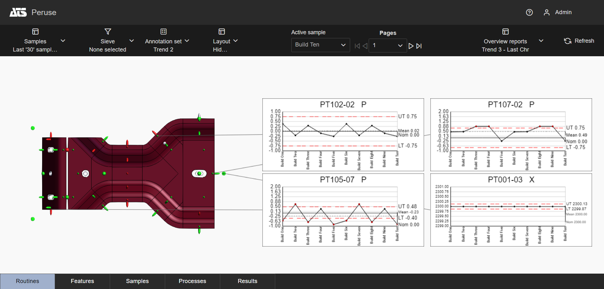
Hide Unused Features - Disabled
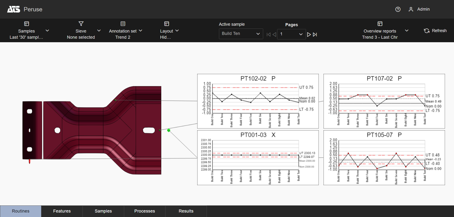
Hide Unused Features - Enabled (default)
The option Zoom to Features may best be utilized in combination with the Hide Unused Features option. This way, the zooming of the 3D model is more focused on the subset of features displayed on the current page, rather than all of the features loaded for the model.
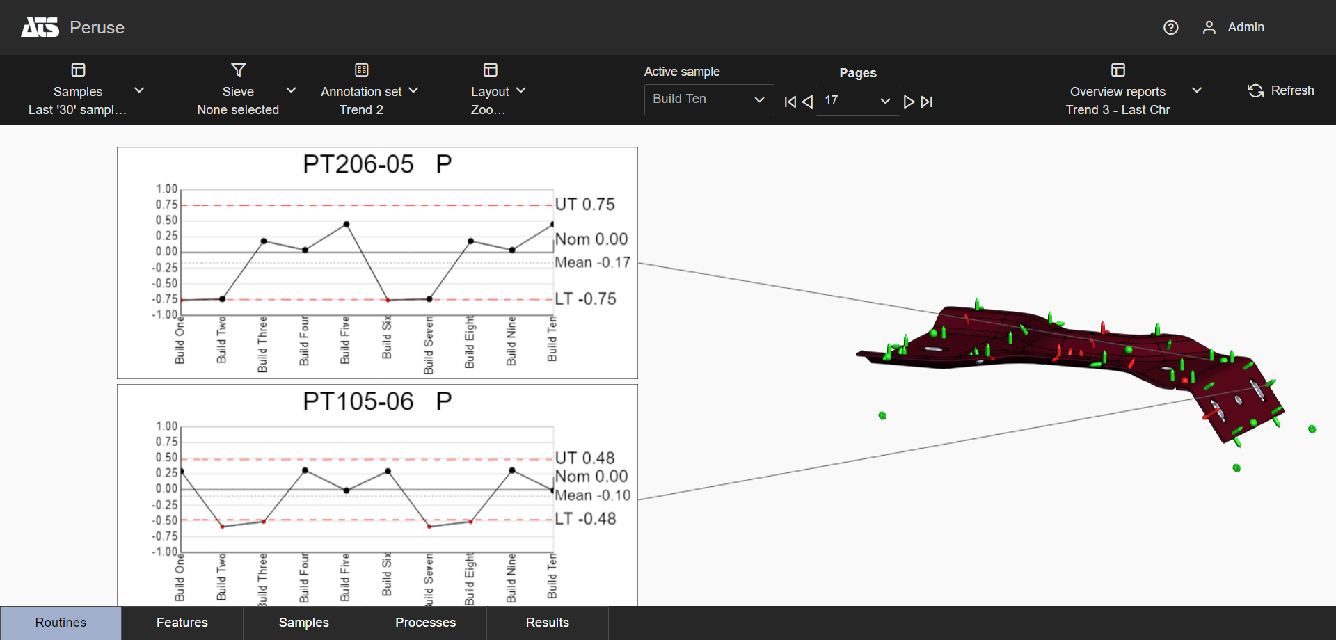
Zoom to Feature with Hide Unused Features Off
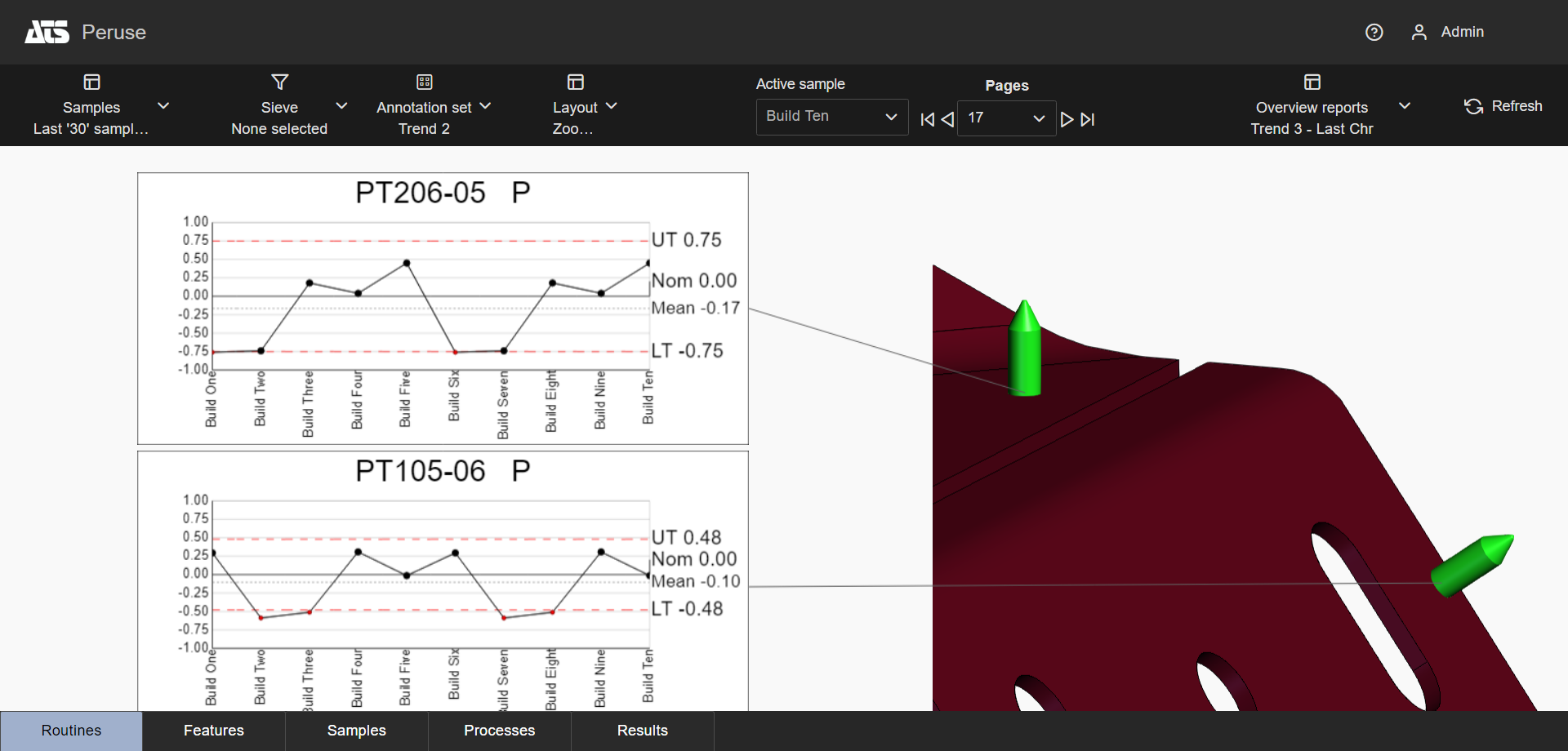
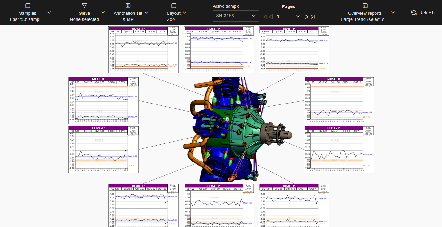
Zoom to Feature with Hide Unused Features On
Automatically orients the 3D model to an optimal position based on the loaded features relative to the annotations in the Layout. The orientation can be done by Plane (XYZ) or by Vector (IJK).
The calculated orientation changes based on what is currently displayed on the page. Switching to a different page, choosing a Sieve, using Cutting Planes or selecting Feature Markers effects the orientation of the model in the view area. This allows users to always have the best view of the feature markers without requiring manual adjustment of the model on each page of the layout.
Manually changing the rotation of the view can only be done temporarily while the viewer is active. Once you exit the active viewer, the model returns to the automatic orientation position. If Zoom to Features is not set for this layout, you can manually change the zoom of the model that will be maintained even when navigating between pages.
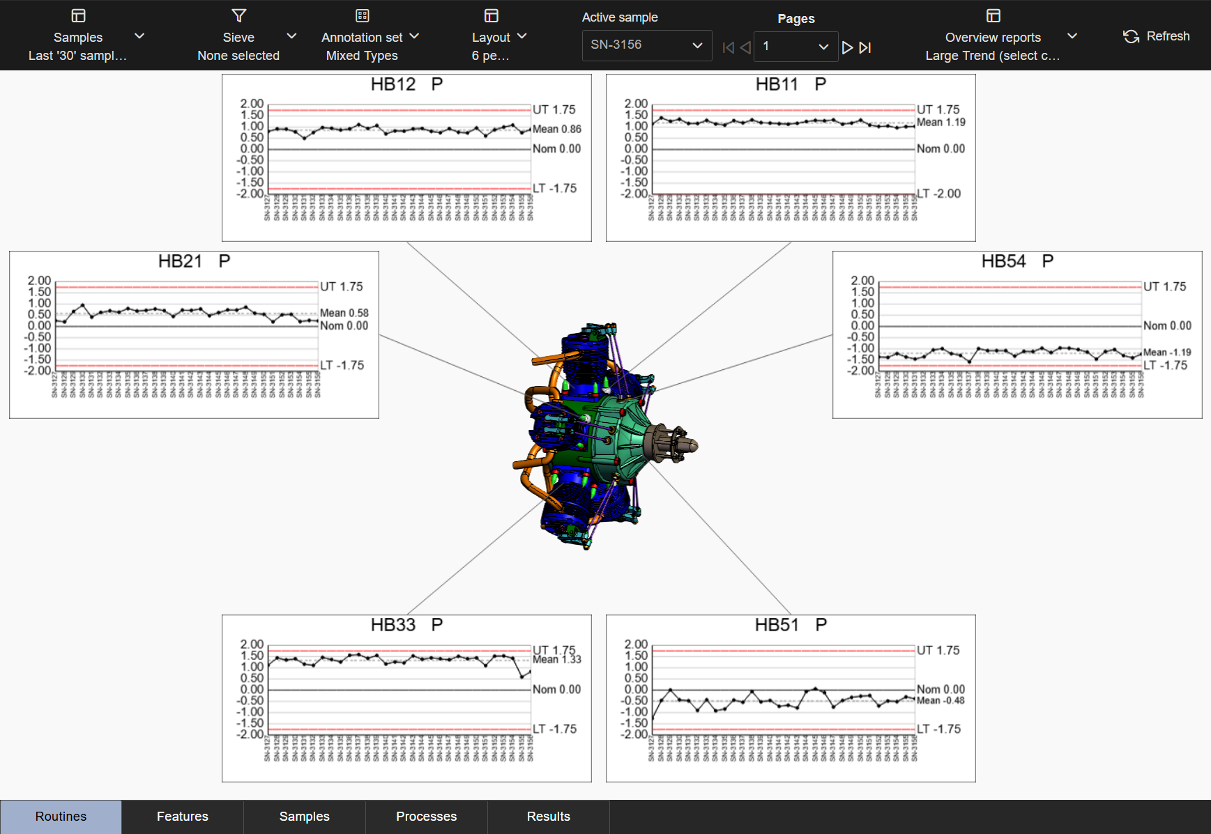
No Auto Orient
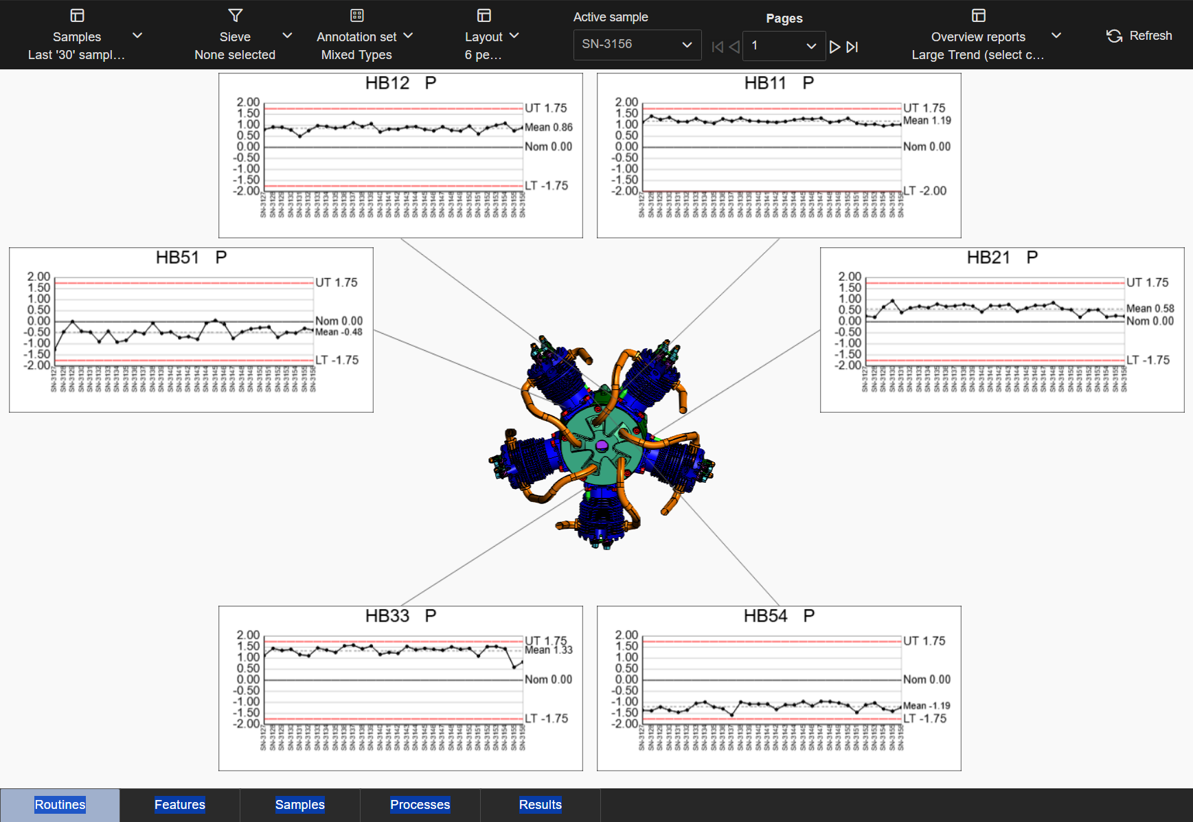
Auto Orient to Feature Plane
Auto Orient to Feature Vector
Automatically adjusts the zoom of the 3D model so the currently displayed feature markers fill the 3D Viewer area. Each page of the layout provides a best-fit zoom to optimize the view area to highlight the features displayed in the annotations.
The calculated zoom changes based on the feature markers displayed on the 3D model. Switching to a different page, choosing a Sieve, using Cutting Planes or keeping/removing Feature Markers effects the zoom of the model in the view area. This allows users to always have the best view of the feature markers without requiring manual adjustment of the model on each page of the layout. If you prefer a closer zoom to the relevant features, consider adding the Hide Unused Features option to eliminate feature markers without an annotation on the current page.
Manually changing the zoom of the view can only be done temporarily while the viewer is active. Once you exit the active viewer, the zoom returns to the automatic zoom position. If Auto Orient is not set for this layout, you can manually change the rotation of the model that will be maintained even when navigating between pages.
Zoom to Features - Disabled (default)
Zoom to Features - Enabled
The option Zoom to Features may best be utilized in combination with the Hide Unused Features option. This way, the zooming of the 3D model is more focused on the subset of features displayed on the current page, rather than all of the features loaded for the model.
Zoom to Feature with Hide Unused Features Off
Zoom to Feature with Hide Unused Features On
Characteristics belonging to one feature are displayed on a single page, preventing the separation of characteristics across different pages. There are some cases where splitting up characteristics between pages cannot be avoided. Layouts with this option disabled have no strict requirement to display all characteristics from one feature on a single page, although the data ordering may result in some characteristics appearing on the same page.
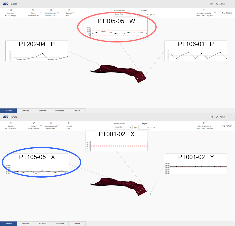
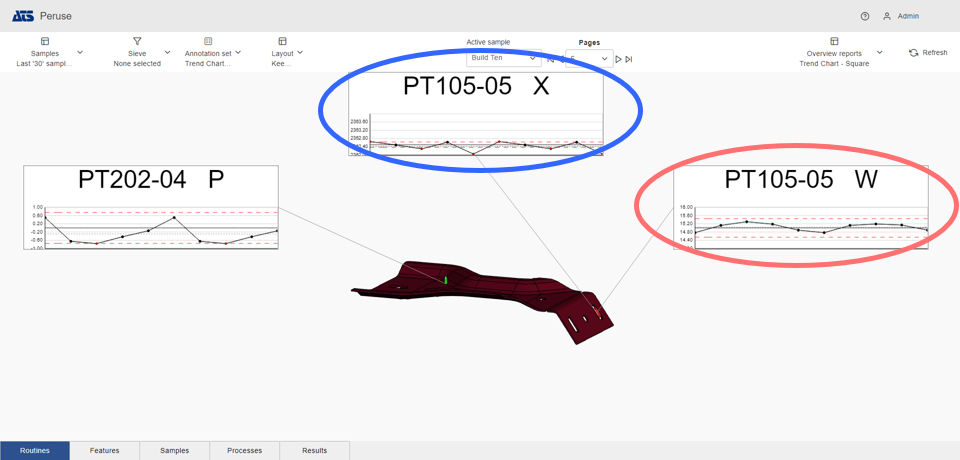
Keep Characteristics Together - Disabled (default): Characteristics may appear on different pages; in this case, chars X and W appear on page 6 and 7.
Keep Characteristics Together - Enabled: Characteristics appear on same page; in this case, both chars X and W appear on the page 6.
In rare instances when the current page exclusively shows characteristics from features containing multiple characteristics, not all characteristics from a single feature might be displayed on that page. This scenario could occur if the selected layout limits the number of annotation charts per page to an amount lower than the largest number of characteristics per feature. Additionally, if one page has exhausted its capacity with characteristics from features containing multiple characteristics as per the layout configuration, any remaining characteristics are placed on the subsequent page.
A full screen option is provided as a system default, where the 3D Viewer fills the screen area and no annotations are displayed. This layout cannot be deleted or modified, but you can create a custom Layout and designate that layout as the default on load.
If the Make Default check box is enabled on any of the user-defined layouts, the Full screen option will not be loaded first.