Layouts are predefined configurations of annotations (charts/graphs) connected by leader lines to feature markers on a 3D model in a central viewer area. Changes to data selection or model adjustment result in immediate updates to the layout contents, including redrawing of leader lines and annotation ordering. The type/style of the annotations in the layout is determined by the selected Annotation Set.
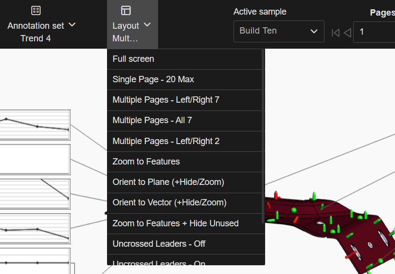
Layout menu
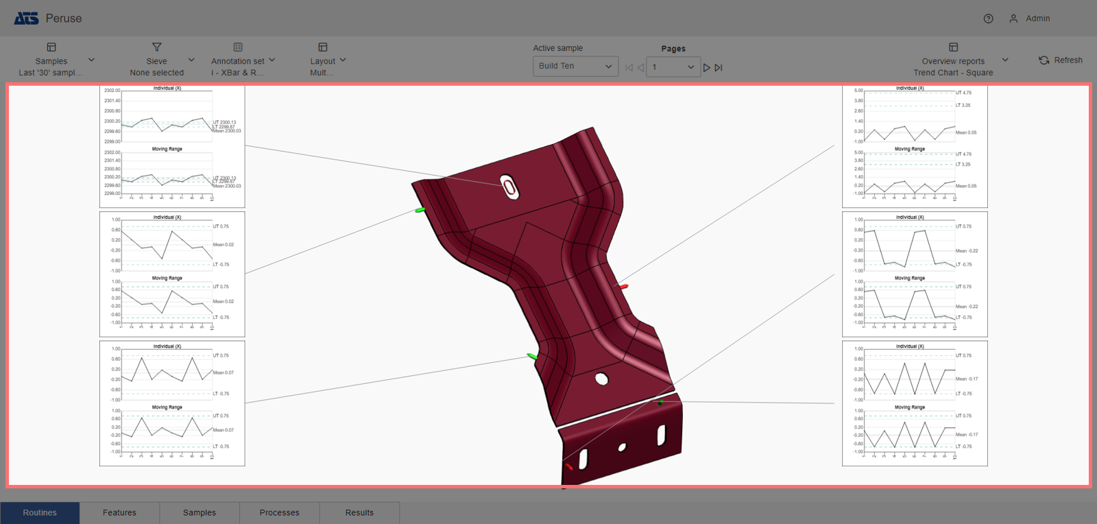
Layout screen area
Layouts can vary in number of annotations, where the annotations are drawn and how the annotation are arranged from page to page. Layouts only determine the placement or sizing of annotations. The annotation type or style is determined by what is currently selected in the Annotation Set dropdown menu. Other behavior options can be configured that determine how the annotations are organized within the screen area or how the layout effects the 3D model. A built-in option called 'Fullscreen' is available without any Admin Configuration, which shows only the 3D Viewer without any annotations.
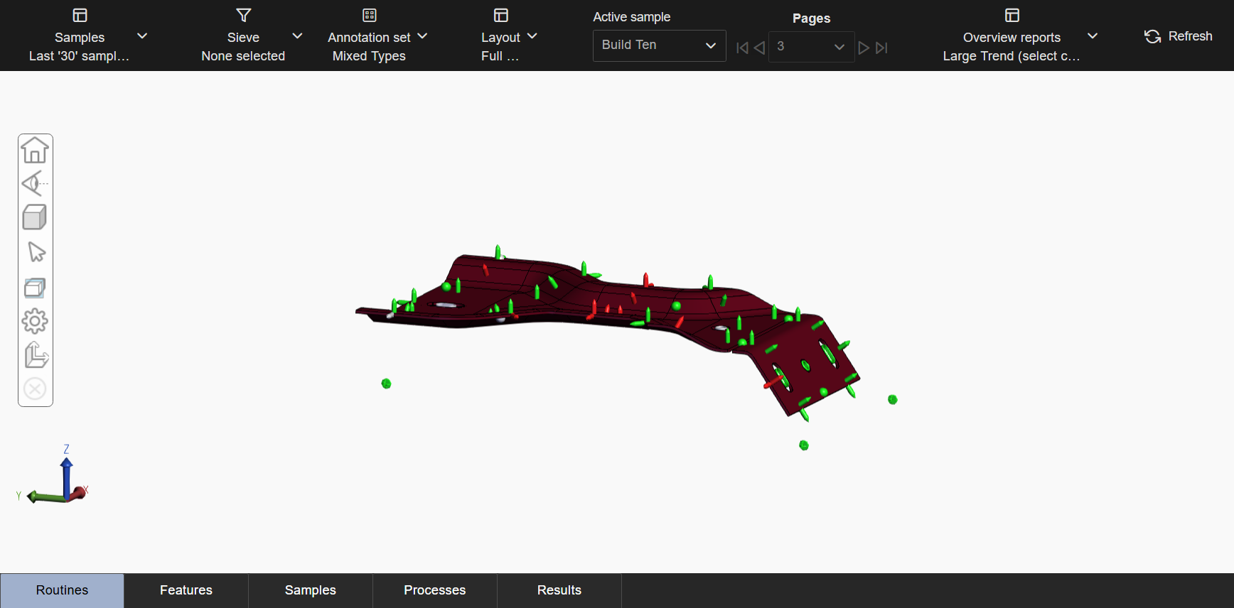
Built-in Layout Full screen - 3D viewer only
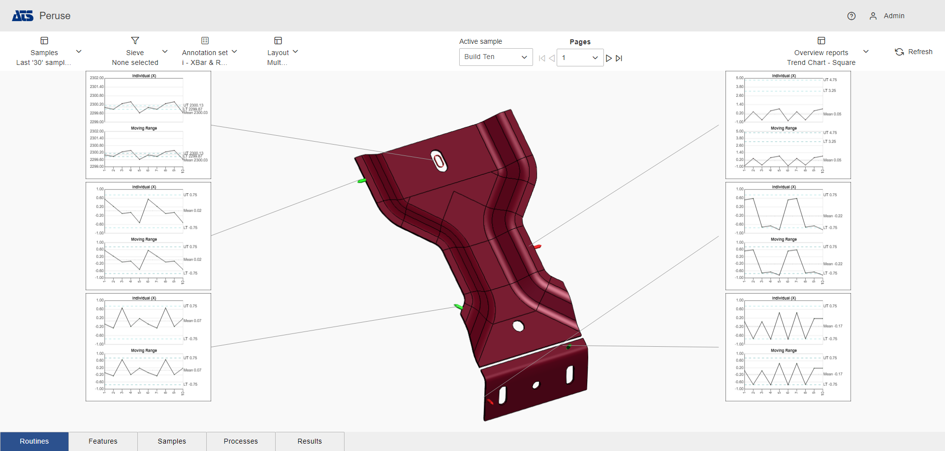
Configured Layout - Left/Right, one column
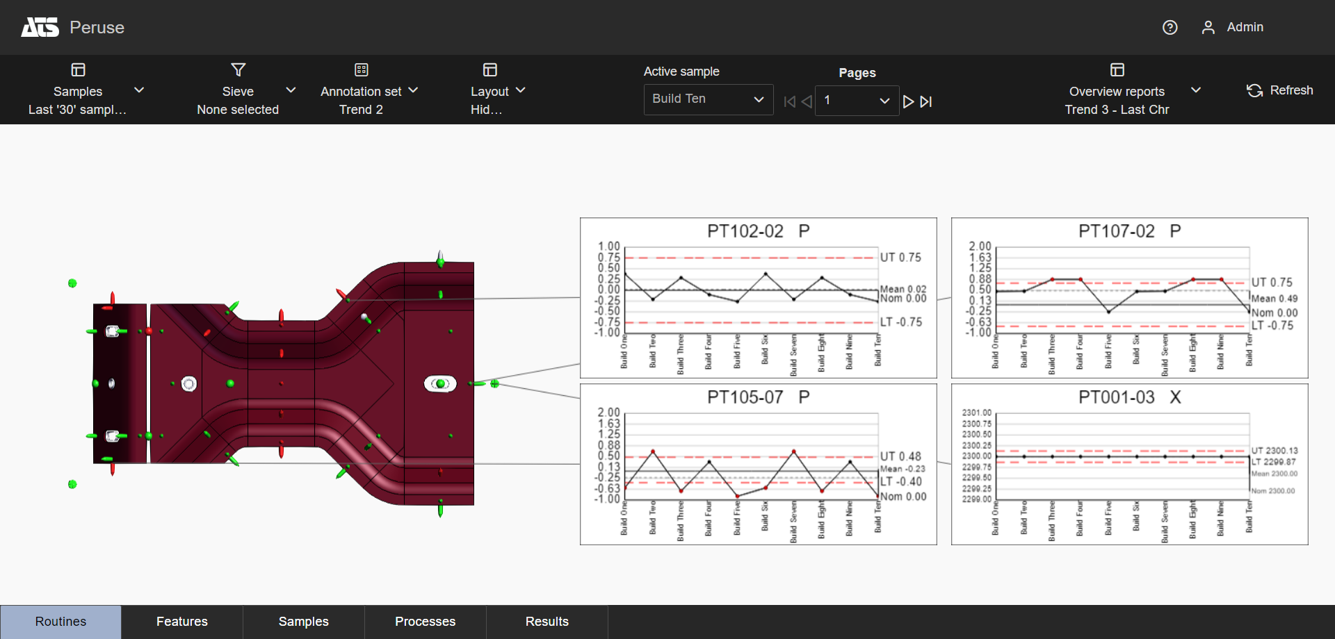
Configured Layout - Right only, two columns
Choose a Layout
To choose a Layout, select an option from the Layouts menu at the top of the 3D Viewer page.
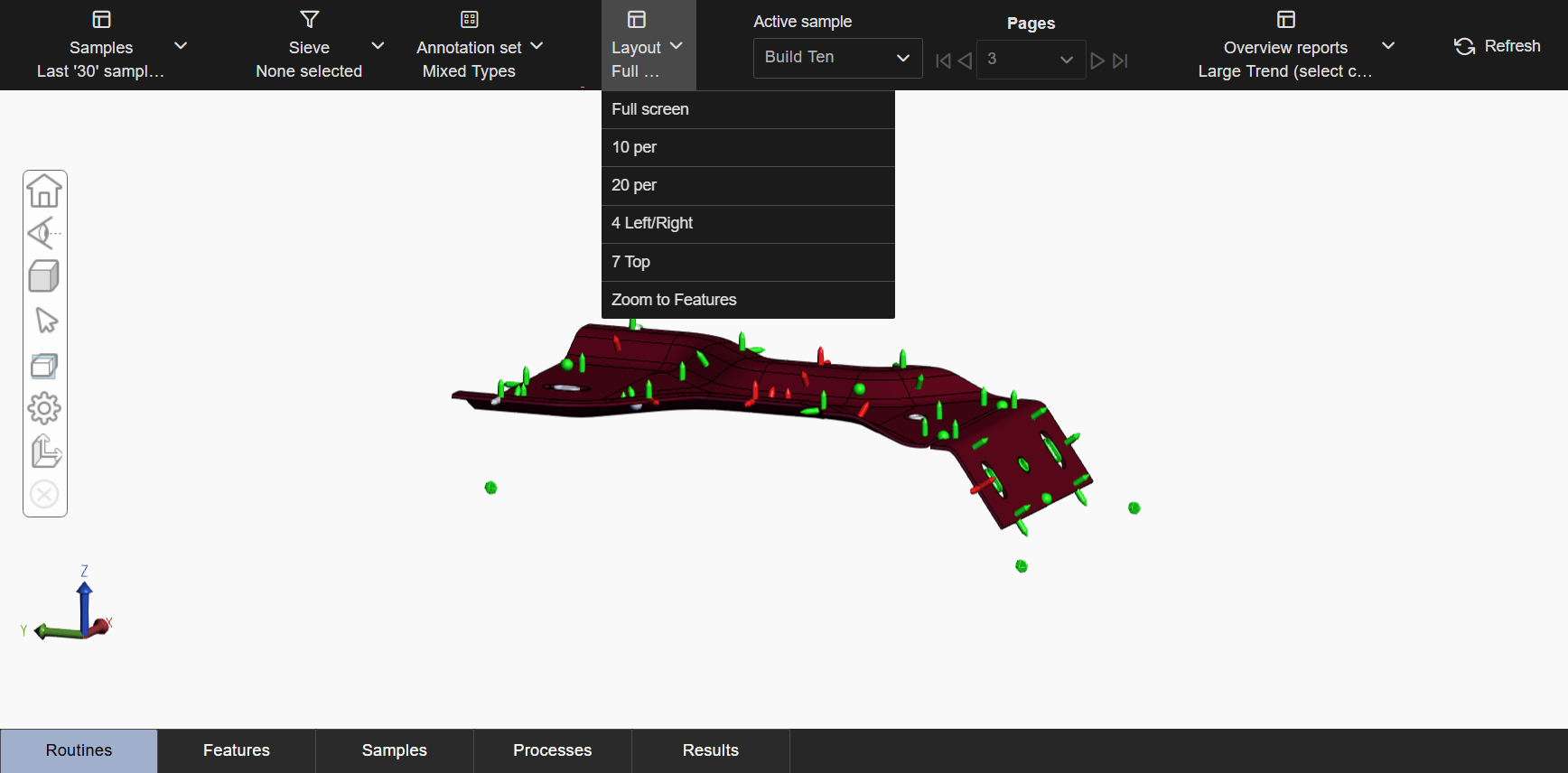
A full screen option is provided as a system default, where the 3D Viewer fills the screen area and no annotations are displayed. This layout cannot be deleted or modified, but you can create a custom Layout and designate that layout as the default on load. It is used when the 3D model is the primary focus or to open individual annotations rather than annotations for the complete set of data.
If Full screen is the only option in the dropdown menu, you must create your Layouts in the CM4D Configuration plugin. See the topic Peruse Layouts Configuration for details.
Choose an Annotation Set
Picking a Layout only determines placement and sizing of annotations, not the type/style of charts or graphs that are drawn. The annotation type or style is determined by what is currently selected in the Annotation Set dropdown menu.
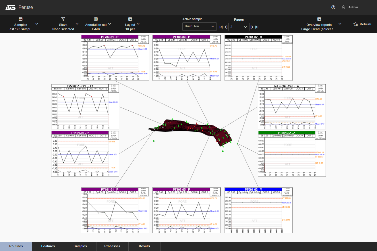
Layout with Annotation Set configured to use the same Annotation Template for all Feature Types
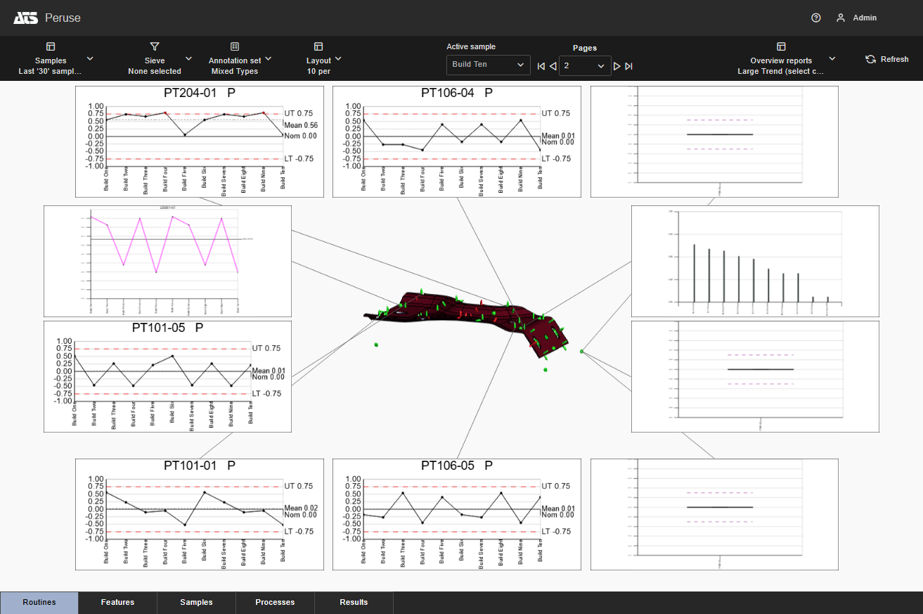
Layout with Annotation Set configured to use the different Annotation Templates for some Feature Types
To choose an annotation style to use in the layout, pick an option from the Annotation Set menu. The annotation set is applied and the layout and is redrawn to accommodate the shape of the annotation templates used by the selected annotation set.
See the Annotation Sets in Peruse topic for more information.
Page Navigation
|
When a Layout has more annotations than can fit on just one page, the Pages toolbar is enabled for navigation between pages. Select another page by clicking the directional arrow or picking the page number from the dropdown. |
First Page | ||
| Previous Page | |||
| Next Page | |||
| Last Page |
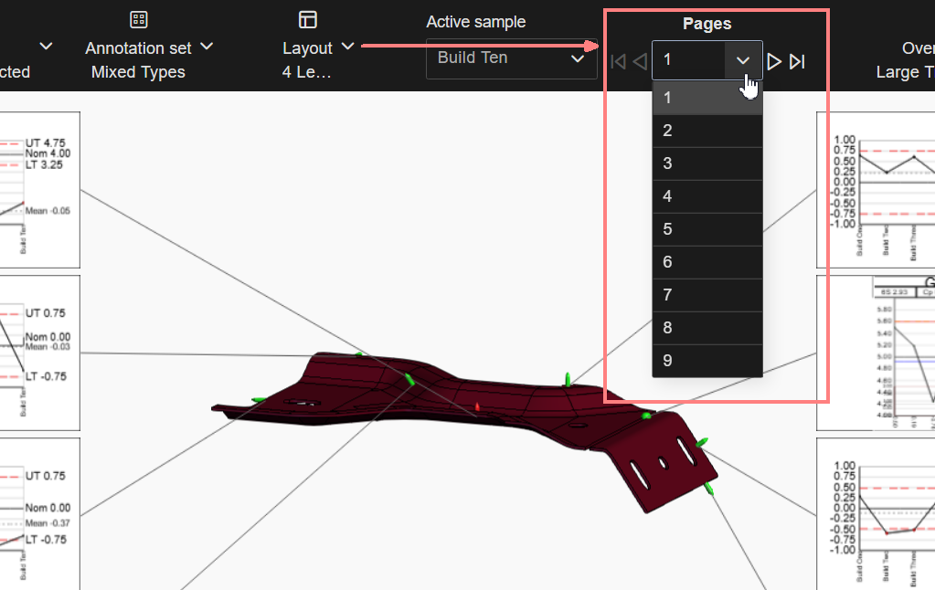
Move forward/backward in sequence, jump to first/last page, or select a specific page from the dropdown.
If there are too many pages to sort through, you can reduce the number of features using Keep/Remove Selected Features filter function on feature markers or in the grids.
3D Viewer - Edit Mode
When using any Layout other than Full screen, the 3D Viewer remains dormant until you manually put the viewer into edit mode. This mode activates the 3D model controls, 3D Viewer Toolbar and feature marker interactions.
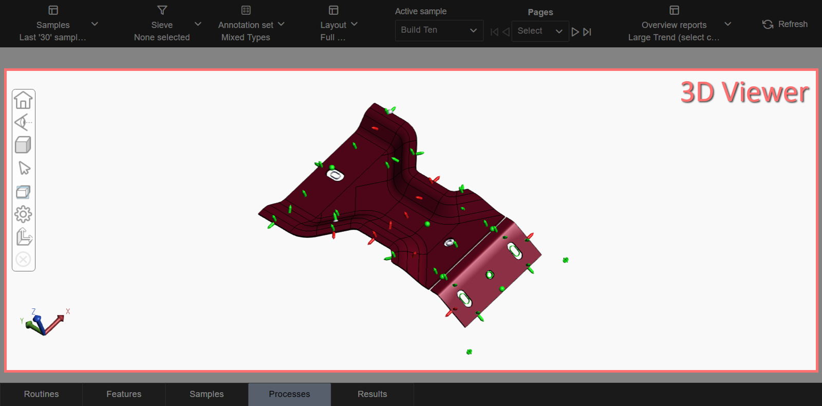
3D Viewer area of the Fullscreen Layout
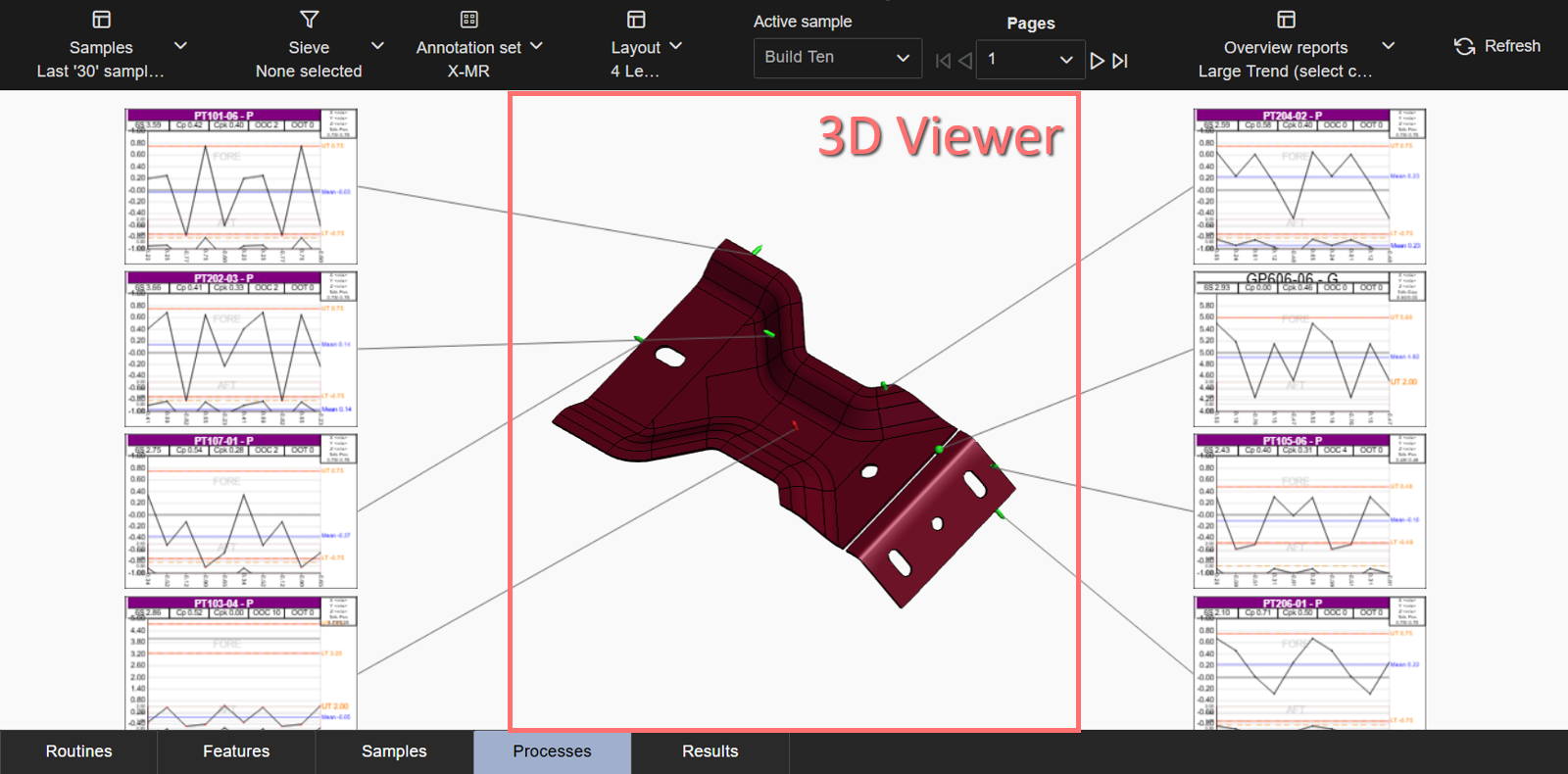
3D Viewer area of a custom Layout
To activate edit mode, double-click any part of the page that contains the viewer area. Once activated, the 3D viewer toolbar is enabled and normal interaction with the model and feature markers is restored.
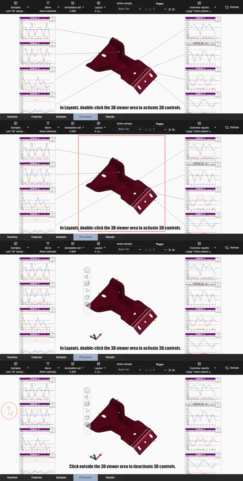
Any rotation or zooming of the 3D model may not be retained upon exiting HOOPS viewer mode. Some layouts may have additional properties configured that can apply automatic adjustments to the rotation or zoom of the model.
Click outside the 3D viewer area to exit edit mode.
Leader Lines
Leader lines attach each annotation with a corresponding feature to a marker on the 3D model. The lines are redrawn on data refresh, switching annotation sets, or after exiting the 3D viewer edit mode.
Annotations for characteristics from the same Feature in certain positions on the same page may share a leader line to the feature marker in the 3D View.
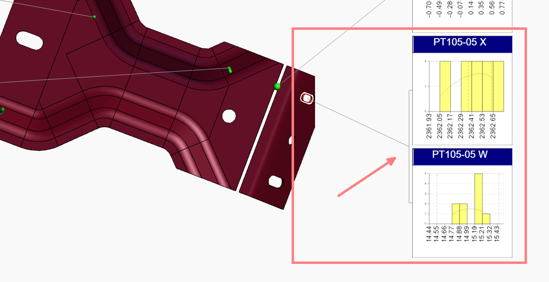
Leader Lines merged for characteristics of the same feature on the same page, provided the layout settings accommodate annotation placement.
Layout Options
While the most notable property of a Layout is the number and placement of the annotations, you may see other behaviors that depend on the options selected by your Administrator when the Layouts were set up in CM4D Configuration.
- Uncross Leader Lines - Leader lines attached to the 3D model are automatically uncrossed each time the 3D View is resolved. Annotations in the Layout are reorganized to accommodate the leaders in the optimal formation to prevent as many crossed lines as possible. This provides an unobstructed view of the 3D model and makes it easier to see which annotation relates to a feature marker. See examplesSee examples
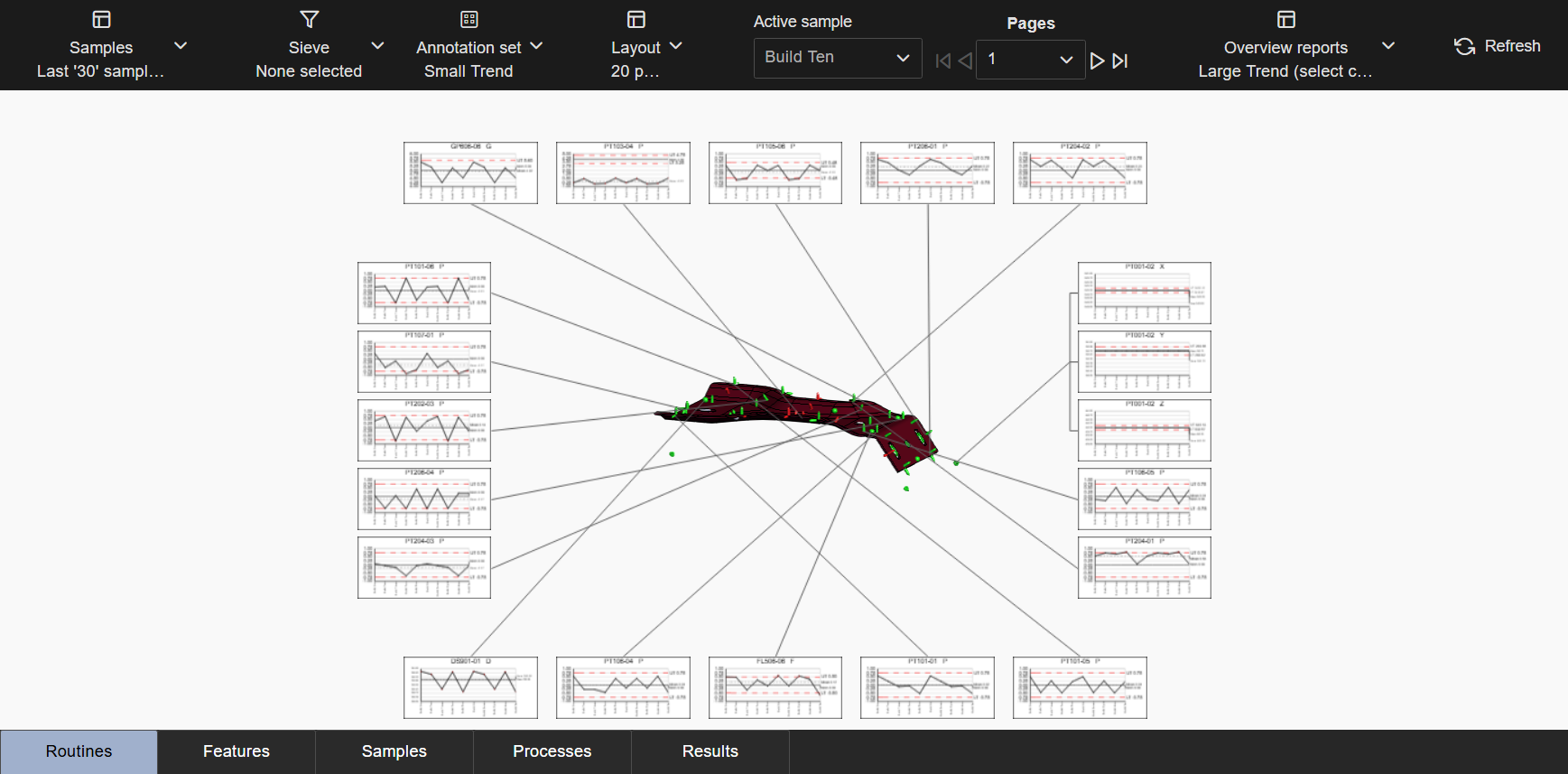
Uncross Leaders - Disabled (default)
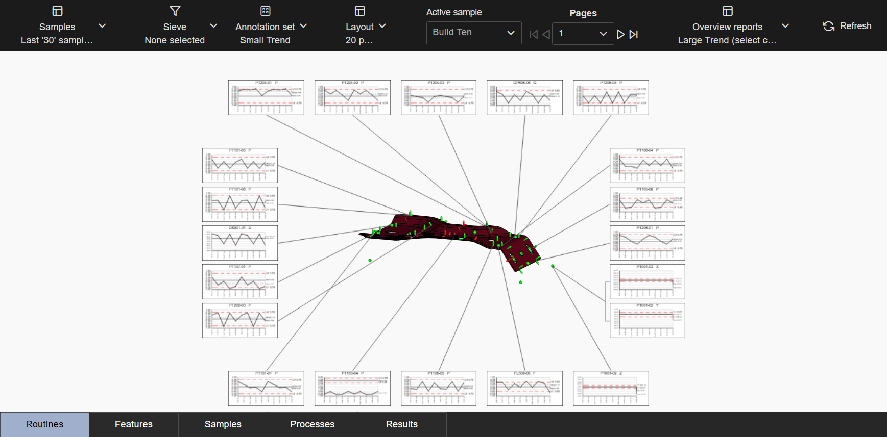
Uncross Leaders - Enabled
- Hide Unused Features - Any features for the 3D model that do not have corresponding annotation on the Layout page are hidden. This is useful for multiple page layouts because only the relevant feature markers are shown on each page. See examplesSee examples
Hide Unused Features - Disabled
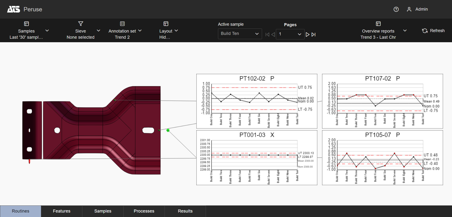
Hide Unused Features - Enabled (default)
- Zoom to Features - Automatically adjusts the zoom of the 3D model so the currently displayed feature markers fill the 3D Viewer area. Each page of the layout provides a best-fit zoom to optimize the view area to highlight the features displayed in the annotations. See exampleSee example
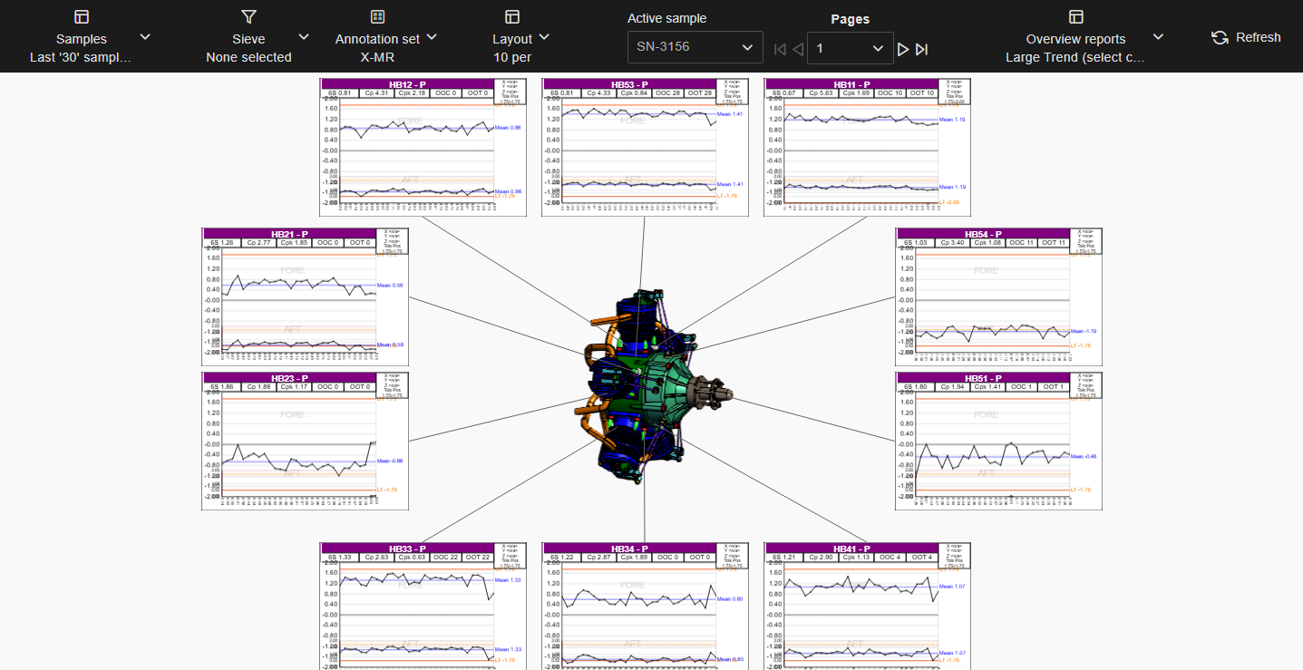
Zoom to Features - Disabled (default)
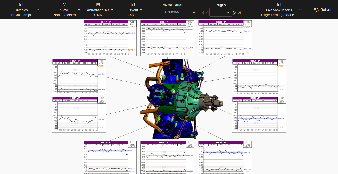
Zoom to Features - Enabled
- Auto Orient - Automatically orients the 3D model to an optimal position based on the loaded features relative to the annotations in the Layout. The orientation can be done by Plane (XYZ) or by Vector (IJK). See examplesSee examples
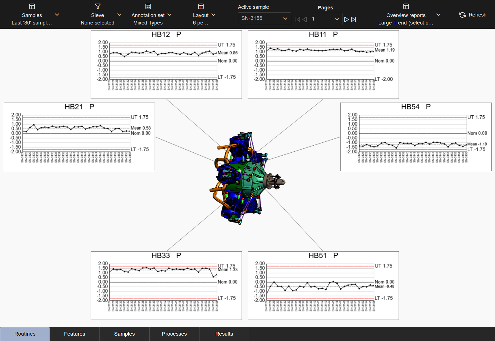
No Auto Orient
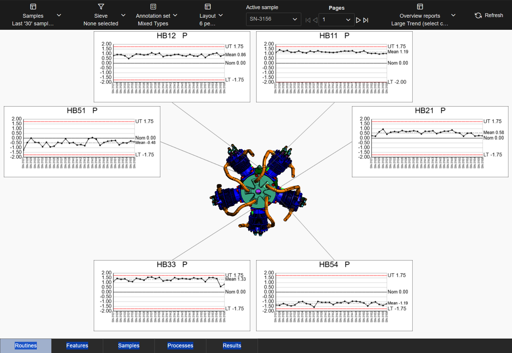
Auto Orient to Feature Plane
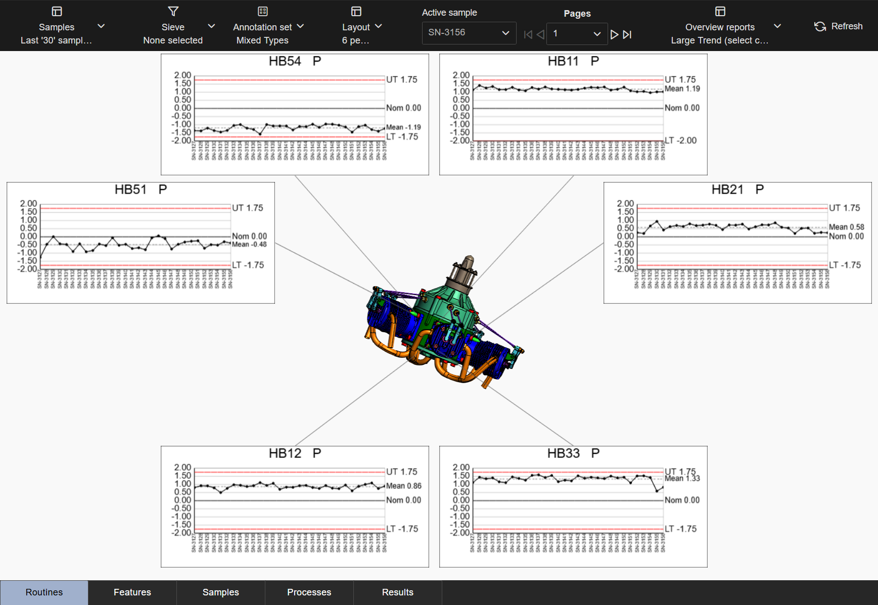
Auto Orient to Feature Vector
- Keep Feature Characteristics Together - Characteristics belonging to one feature are displayed on a single page, preventing the separation of characteristics across different pages. There are some cases where splitting up characteristics between pages cannot be avoided. Layouts with this option disabled have no strict requirement to display all characteristics from one feature on a single page, although the data ordering may result in some characteristics appearing on the same page. See examplesSee examples
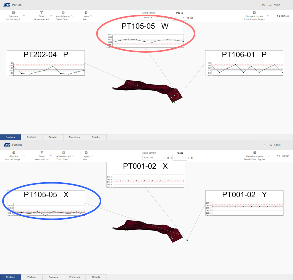
Keep Characteristics Together - Disabled (default): Characteristics may appear on different pages; in this case, chars X and W appear on page 6 and 7.
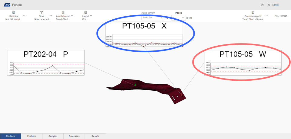
Keep Characteristics Together - Enabled: Characteristics appear on same page; in this case, both chars X and W appear on the page 6.
Layouts in Peruse are configured by a CM4D Administrator in ATS Configuration Manager. See here for more Admin information.
Can we improve this topic? Click Send Feedback in the upper right of the screen to share your comments!