Topic Contents: Hide
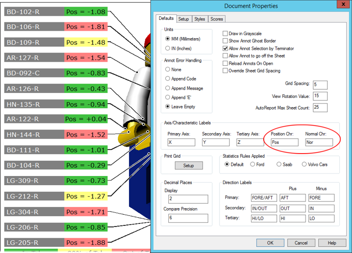
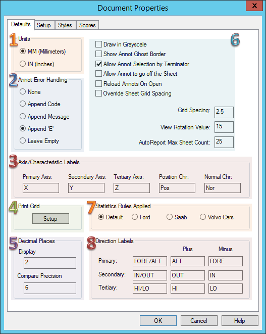
The Defaults tab of the Document Properties dialog contains options for changing the default (or base) settings of a CM4D document.
Click on the image below to learn more about the various sections of this dialog.
· OK - Even if no changes are made, clicking OK (or the red X in the upper right corner of the dialog) will still refresh the values.
· Close - Replaces the OK button after changes are made, saves the values and closes the Document Properties dialog.
· Cancel - Allows you to view the Document Properties and close the dialog instantly without writing out the values again. After opening the Sift Rules or Print Grid Setup dialogs, you can keep from committing those settings by clicking Cancel in those dialogs.
Select the default measurement unit you wish to use throughout your document:
· MM (Millimeters) - Metric unit of length
· IN (Inches) - Imperial unit of length
The Annot Error Handling options determine how errors are displayed when something goes wrong inside an annotation. The Error Handling setting tells CM4D what to display when expected data is not found. CM4D’s response will depend on which of the following options is selected.
If you are going to be exporting data from CM4D to a .csv file, it is recommended that you change the error handling to None to avoid adding an extra comma to a .csv file.
· None
Refer to the topic Error Codes for a complete list of codes and descriptions
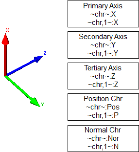
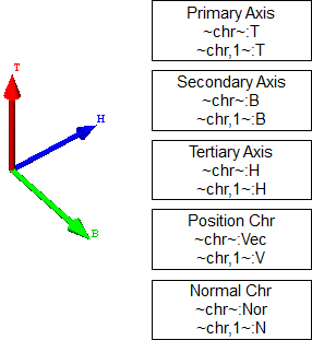
If you wish to use something other than X, Y, and Z for your axis labels, you can enter new values in the fields. The new values will be used as the axis labels, and will be displayed in any views. When using custom labels, CM4D will replace any of the standard X, Y, or Z with the user-defined values.
| Default Axis Labels | Custom Axis Labels | |
|
|
|
|
For example, in an instance where the letters X, Y, and Z are replaced with the letters T, B, and H (respectively), if the variable ~chr~ is used in the document, rather than returning X as the characteristic, the custom letter T will be shown.
See also, View Axes.
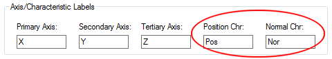
A control has been added to the Document Defaults that allow you to customize the characteristic label that will be used for Position or Nominal characteristics. This label will be used to display the Position or Nominal characteristic when used with variables such as ~chr~ and ~chr,1~. By default, these are set to “Pos” for Position and “Nor” for Normal.
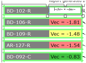
Default Setting Example - show/hide
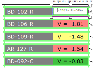
Modified Setting Example - show/hide
For example, if you wanted to use “Vec” as the label for your Position characteristics, you would enter the label text into the Position Chr field in the Document Defaults.
· The variable ~chr~ would resolve as “Vec”. show/hide
· The variable ~chr,1~ would resolve as “V”. show/hide
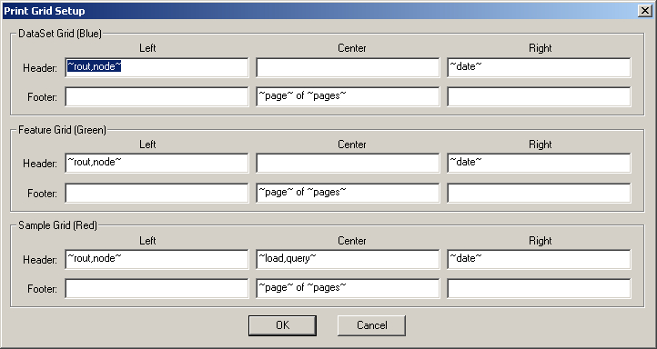
When creating templates for CM4Di, the header and footer of the DataSet's Feature and Sample Grids can be formatted using the Print Grid Setup dialog. CM4D variables can be used in the fields of the header and footer. Non-variable text entered in the fields will appear as it does in the fields. The variables shown below are default variables provided in the CM4D.ini file. If you would like to change the default variables, they can be edited in the CM4D.ini file. Otherwise, enter different variables and/or text in the fields as desired and then click the OK button to save your changes and return to the Document Properties dialog.
If you would like to change the number of decimal places, for either Display or Compare Precision, enter a new value. The Display and Compare Precision field default values can be modified in the [defaults] section of the cm4d.ini file.
The Display value will determine the number of decimal places that will be shown when data is displayed in CM4D. The default number of decimal places is 2.
Compare Precision will be used in CM4D to eliminate the insignificant digits of numbers (caused by measurement/conversion inaccuracies, computer arithmetic precision or computer round-off error) that are used in determining whether values have exceeded a threshold limit. This value can be accessed with the variable ~compareprecision~.
Compare Precision affects the following calculations places in CM4D: DataSet ROV, DataSet Sorting, Table Sorting, Events, OOC (including mid-third) and OOT, Box and Whiskers, Transforms, DataStack Tally, DataStack Scores, DataStack Bins, DataStack Benchmarks, Unreasonable data checks (Causes), and Variables (devdir, cardir, meandir, meancardir).
When data is being sorted in CM4D, the values will be compared up to the decimal number set in the Compare Precision field. For example, the default number 6 would compare up to the sixth decimal places (i.e. 0.000001). Values beyond the sixth decimal place are generally considered insignificant and should therefore be discarded.
When a value of 1.5000000000001 is compared to an upper tolerance value of 1.5, the value would be considered out of tolerance because it is above the tolerance value. In this situation, if the compare precision integer is set to 6, the value 1.5000000000001 will only be compared as 1.500000 and will therefore be within tolerance.
When Draw in Grayscale is selected in the Document Defaults, the annotation within the document will be displayed in grayscale. All portions of an annotation which have been assigned a color, such as a text color or a brush color, will appear as a corresponding shade of gray.
When Show Annot Ghost Border is selected, a gray dashed border will appear around any annotation that have a border style set to None. Normally, when an annotation has None selected as the border style, no border will appear. The example below shows a text box that has had its border set to None. When the Show Annot Ghost Border check box is selected in the Defaults page of the Document Properties dialog, the border of the text box will appear as a gray dashed line.
When enabled, annotation can be selected by clicking on their terminators. If several annotation have terminators in the same area, clicking more than once in the same spot will toggle to the next annotation.
When Allow Annot to go off the sheet is turned on, annotation can be placed off of the sheet (on the green area). When this option is turned off, any annotation dragged and dropped off the sheet will snap back to the nearest sheet margin.
This option, which is off by default to support backwards compatibility, can also be set in the [defaults] section of the Cm4d.ini file: allow_annot_off_sheet=0
When Reload Annots On Open is selected, all annotation which load from annot templates will be reloaded each time the document is opened. In order for this to work, however, the check box Eligible for Reload on Document Open must be selected in the General tab of the Annot Properties dialog for each annotation.
See the topic Create Annotation Templates for more information.
When Override Sheet Grid Spacing is selected, the default Grid Spacing will be used for all sheets, even those sheets which have custom grid sizes set. When this option is set, the check box in the sheet Grid Spacing dialog will be selected to indicate that the Document Defaults Grid Spacing is overriding the sheet-level grid size. If the Override Sheet Grid Spacing is disabled, then all sheets will revert to their original grid spacing setting (whether using the original default or sheet-level).
See the topic Menu Bar - Sheet for more information.
The value entered in the Grid Spacing field is the default Grid Size for all sheets within a document. If an individual sheet is customized to use a specific grid size, the default grid spacing will not be used for that sheet (exception: see Override Sheet Grid Spacing).
The rotation value (n) will rotate the image n° (degrees) at a time when rotating an image within the View.
The default rotation value of 15 will rotate the image 15° at a time.
The number of sheets that Auto Report will generate can be limited by entering the maximum number of sheets you want to be generated in the Max Sheet Count field. If you are creating a CM4D document for use in CM4Di, the Max Sheet Count entered here will be applied to the CM4Di document.
See also, Auto Report.
Users can chose whether to use different sets of statistical rules. See the topic Statistics Rules for more information about each set of rules.
The Direction Labels will display the direction of check. If you do not wish to use the default direction labels, enter new values in the fields. The labels assigned will be returned when variables are used. The axis labels are also used in the Feature Editor, when editing Limits, as additional labels for High and Low values.
See the topic Feature Editor - Creating/Editing Limits for more information.