1. Open a new CM4D document.
3. Create a new Query.
4. Load the Simple Block ^ ?H routine.
5. Open the Query Properties and click the Edit Subroutines and Alignments and load the Sub Block subroutine that was created in Phase 2.
6. Load all available samples and order them by Label.
7. Activate the first sample by right-clicking the sample label in the tree bar and selecting Activate from the menu.
1. Expand the Features node under the Query node in the data tree.
2. Right-click on the Simple Block routine node and select Properties from the menu.
3. On the Image tab, select the 3D Image radio button, and then browse to the file Simple Block.xgl.
4. Click the OK button to close the Routine Properties dialog.
1. Create a DataSet with the following properties:
2. Use the query as a DataSource.
3. Use All Features.
4. Use Active Sample.
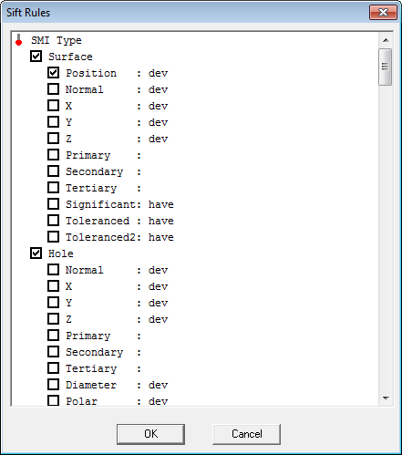
5. Change Sift Rules to only use the Primary characteristic of the Surface Points, and the Primary and Secondary characteristics for Holes and Slots.
6. All value types for X, Y, and Z should be set to dev. The characteristic value may be locked due to the AllowTypeSet settings in your cm4d.ini file.
7. Set the event trigger to ValueNotBetween.
8. Set the trigger values to .25 and -.25.
9. Select the Trigger on Active Sample check box.
10. Close the DataSet Properties dialog to apply your changes.
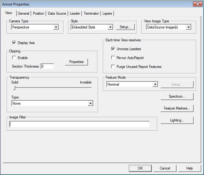
1. Right click on the View and select Properties from the menu.
2. On the Annot Properties View tab, change the View Image Type to DataSource Image.
3. Select the Re-run AutoReport check box and click OK.
4. On the DataSource tab, change the DataSource to the DataSet that was created in Step 3.
5. You may need to Zoom the view in order to see the image in the document region .
1. Create a Document Properties Style labeled TriggeRED.
2. On the Brush tab, change the color to Lt Red.
3. On the Font tab, change the Point Size to 20.
1. Create
a Text Annotation using the Text ( )
tool.
)
tool.
2. On the Text tab, in the empty text field, enter the following variables:
a. ~label~
b. ~dev~
3. Click the Setup button in the Styles region of the Text tab and set the font point size to 20.
4. On the DataSource tab, set the DataSet created in Step 3 as the text annot DataSource.
5. Set the DataSource to use Row 1.
6. Set the Leader to use the DataSource feature in the view.
7. Set the Event Action in the General tab to Use Style TriggeRED.
8. Box size is 50 wide by 20 high.
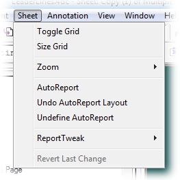
1. To open the Auto Report Properties dialog, select Auto Report from the Sheet menu.
2. Select the Text Annot just created from the Report Annot dropdown.
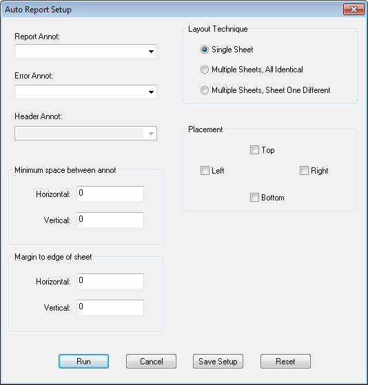
3. Set the Placement to Allow on Left and Allow on Right.
4. Change minimum space to 1 and Margin to 4.
5. Click the Run button.
6. Your document should resemble the following:
To save your document, select Save As in the File menu.