3D Viewer Tools

Topic Contents [Hide]Topic Contents [Show]
  1. 1. Annotation Scale
  2. 2. Camera Menu
  3. 3. Close Annotation
  4. 4. Cutting Planes
  5. 5. Display Mode
  6. 6. Feature Marker Settings
  7. 7. Fit
  8. 8. Selection Mode

The 3D Viewer Tools are used to manipulate the 3D model in the viewer. The tools are located in a vertical toolbar on the left side of the main view area where the 3D model is displayed. The toolbar becomes semi-transparent when it is not actively in use.

8. Selection Mode 
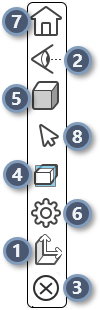
The toolbar includes the following viewer tools:
  1. Annotation Scale - Modify the size of the annotation open within the 3D viewer. This may be used if the initial annotation size is not ideal for the zoom level you prefer for the model.
2. Camera Menu - Preset camera options to quickly move the model to a preset orientation.
3. Close Annotation - Closes all open annotation attached to the Feature markers in the 3D View. This button is disabled until at least one annotation is open.
4. Cutting Planes - Add or remove cutting planes on the 3D model.
5. Display Mode - Changing the visual appearance of the 3D Model.
6. Feature Marker Settings - Feature marker modes and resolutions.
7. Fit - Resets the model so it is zoomed (in or out) to the extent it fits within the viewer area (aka, zoom max).
8. Selection Mode - Change the cursor mode between single click and area for selecting Feature Markers.

1. Annotation Scale

The Annotation Scale setting allows you to modify the size of the annotation open within the 3D viewer. This may be used if the initial annotation size is not ideal for the zoom level you prefer for the model.

The default is 10, but you can enter any number greater than 1 to adjust the scaling factor relative to the original size of the annotation. Click Apply to see the result of the scale, then Close to exit the dialog.

This scale is not applied to annotation configured using a manual scaling. If your charts do not seem to be changing scale, contact your CM4D administrator who designed the annotation used in Peruse.

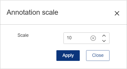
Annotation Scale - 10 [default]

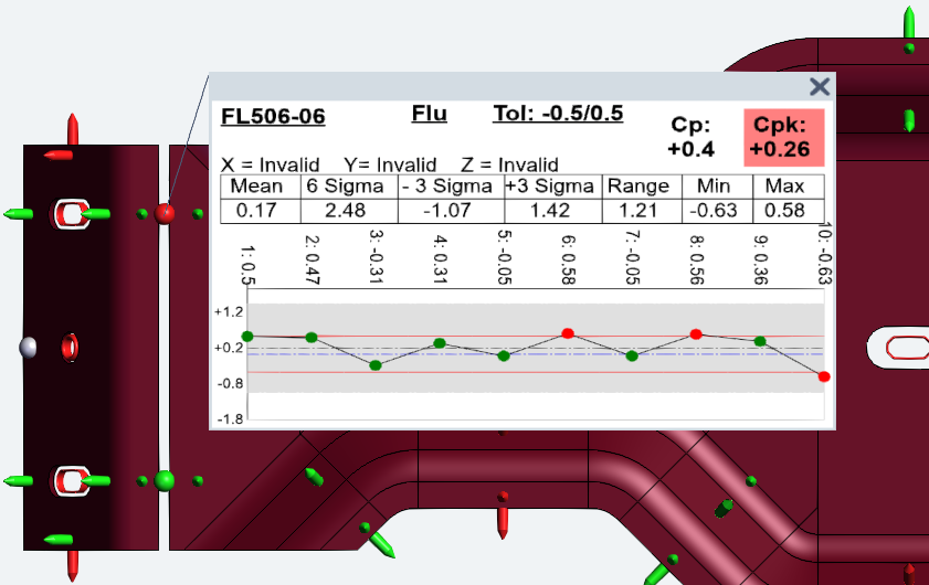
Annotation Scale - 50

See also, Annotations in the 3D Viewer.

2. Camera Menu

The Camera Menu provides preset camera options to quickly move the model to a preset orientation.

Name Icon Description
Iso View Isometric view orients the model so the angles between the XYZ axes are equal.
Orthographic Projection This projection displays the view in a fixed depth. The model does not scale X and Y coordinates depending on the Z coordinate so the direction of the projection is perpendicular to the camera target plane.
Perspective Projection This projection displays the view with depth. The model scales the X and Y coordinates depending on the Z coordinate (depth) so objects that are further away appear smaller on the screen.
Left View Orients the model to view the left side (ZX).
Right View Orients the model to view the right side (XZ).
Bottom View Orients the model to view the bottom (YX).
Front View Orients the model to view the front (ZY).
Back View Orients the model to view the back (YZ).
Top View Orients the model to view the top (XY).

See also, Peruse 3D Viewer Camera.

3. Close Annotation

Close Annotation closes all open annotation attached to the Feature markers in the 3D View. This button is disabled until at least one annotation is open.

4. Cutting Planes

The Cutting Plane tools allow you to add or remove cutting planes on the 3D model. To open the fly-out menu, click the fifth icon from the top of the viewer toolbar.

Name Icon Description
Toggle X Plane Toggles the cutting plane along the X axis on/off.
Invert X Plane Enabled when the X plane is active. Flips the cutting plane to cut the geometry in the opposite direction along the X axis.
Toggle Y Plane Toggles the cutting plane along the Y axis on/off.
Invert Y Plane Enabled when the Y plane is active. Flips the cutting plane to cut the geometry in the opposite direction along the Y axis.
Toggle Z Plane Toggles the cutting plane along the Z axis on/off.
Invert Z Plane Enabled when the Z plane is active. Flips the cutting plane to cut the geometry in the opposite direction along the Z axis.
Show/Hide Planes Enabled when at least one cutting plane is active. Toggles the visibility of the cutting plane bounding box. By default, the cutting plane reference box is visible. While the plane is hidden, it cannot be moved.
Toggle Quadrants Enabled when two or more planes are active. Toggles the cutting planes from a single cutting section to separate cutting sections.
  • OFF - All enabled planes are combined to act as a single cutting plane; cuts all geometry intersected by any plane.
  • ON - Each enabled plane acts an individual plane; cuts only geometry intersected by all planes.
Reset Enabled when at least one cutting plane is active. Sets all cutting plane locations to default and turns off all cutting planes.
 

See also, Peruse Cutting Planes.

5. Display Mode

The Display Mode toolbar has options for changing the rendering of the 3D Model to one of four predefined modes. A flyout menu contains the four options; the icon for the current mode is shown in the toolbar.

Name Icon Description
Shaded with Lines [Default Mode] Sets the rendering mode to Phong Shading with Lines. This mode displays the model geometry as shaded and opaque, with the addition of visible, unobscured lines. Colors are obtained from the CAD file. This is essentially a combination of the Shaded and Hidden Lines modes. This mode may display some parts better than just Shaded.
Shaded Sets the rendering mode to Phong Shading. Colors are obtained from the CAD file. This mode displays the model geometry as shaded and opaque.
Hidden Lines Sets the rendering mode to Fast Hidden Line. This mode displays only visible, unobscured lines. Faces of visible geometry are used to obscure the lines in the model. All color defined in the CAD file is turned white. This mode is a simple view that may provide a better result for hardcopy or screenshots.
X-Ray Sets the rendering mode to X-Ray. This mode displays the model geometry as semi-transparent, but not the feature markers. This mode allows you to see through a complex scene to view or select the Feature markers.
 

See also, Peruse 3D Viewer Display Modes.

6. Feature Marker Settings

The Feature Marker Settings include options for Feature marker modes and resolutions. These options may effect the load-time performance for Feature markers.

Setting Description
Mode Select the shape of the feature markers appearing in the 3D Viewer:
  • Feature Specific - The marker appearance is determined by the feature type; each feature type has a unique, identifiable marker shape. See here for examples.
  • Sphere - A generic sphere marker is used for all feature types. Use this setting if you encounter performance issues in the 3D Viewer.
Resolution Select the quality of the feature markers:
  • High - Render the feature markers with the highest quality.
  • Low - Render the feature markers with a lower quality. Use this setting if you encounter performance issues in the 3D Viewer.
Scale Apply a multiplier to the overall size of the feature markers; default is 10. This option is included in the algorithm used by the auto scale.
Use Auto Scale Enable to allow CM4D to determine the optimal feature marker scale according to size of the model. This automatically adjusts overall marker size while still applying the set scale into the algorithm.
 

See also, Peruse Feature Marker Settings.

7. Fit

The Fit button resets the model so it is zoomed (in or out) to the extent it fits within the viewer area (aka, zoom max). For Exchange files, this activates the default view.  

8. Selection Mode

The Selection tools are used to select feature markers on the 3D model. Choose a selection tool to change the cursor between single click and area select.

Name Icon Description
Select Allows single click interactions with the model, such as manipulating the view position or selecting individual feature markers. Can be used in conjunction with the Ctrl key to select multiple feature markers one at a time.
Area Select Allows a click & drag action to draw a square around an area of the model to select the feature markers within that selection zone.
 

Related Concepts:

Annotations in the 3D Viewer

Peruse Cutting Planes

Peruse 3D Viewer Display Modes

Peruse Feature Marker Settings

Peruse 3D Viewer Camera

Related Reference:

Peruse Feature Markers


Can we improve this topic?